


Video Capture Registers
3-61Video Capture PortSPRU629
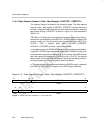
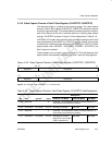
3.13.5 Video Capture Channel x Field 2 Start Register (VCASTRT2, VCBSTRT2)
The captured image is a subset of the incoming image. The video capture
channel x field 2 start register (VCASTRT2, VCBSTRT2) defines the start of
the field 2 captured image. (This allows different window alignment or size for
each field.) Note that the size is defined relative to incoming data (before
scaling). VCxSTRT2 is shown in Figure 3–33 and described in Table 3–18.
In BT.656 or Y/C modes, the horizontal (pixel) counter is reset by the horizontal
event (as selected by the HRST bit in VCxCTL) and the vertical (line) counter
is reset by the vertical event (as selected by the VRST bit in VCxCTL). Field 2
capture starts when HCOUNT = VCXSTART, VCOUNT = VCYSTART, and
field 2 capture is enabled.
These registers are not used in raw data mode or TSI mode because their
capture sizes are completely defined by the field 1 start and stop registers.
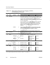
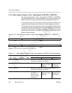
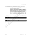
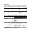
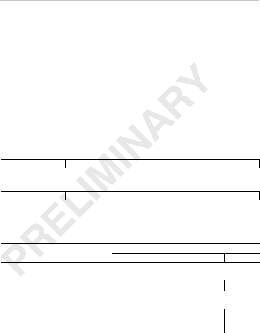
Figure 3–33. Video Capture Channel x Field 2 Start Register (VCASTRT2, VCBSTRT2)
31 28 27 16
Reserved
VCYSTART
R-0 R/W-0
15 12 11 0
Reserved
VCXSTART
R-0 R/W-0
Legend: R = Read only; R/W = Read/Write; -n = value after reset
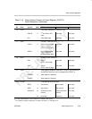
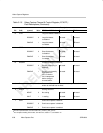
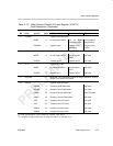
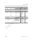
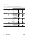
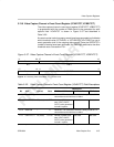
Table 3–18. Video Capture Channel x Field 2 Start Register (VCxSTRT2) Field Descriptions
Description
Bit field
†
symval
†
Value BT.656 or Y/C Mode Raw Data Mode TSI Mode
31–28 Reserved – 0 Reserved. The reserved bit location is always read as 0. A
value written to this field has no effect.
27–16 VCYSTART OF(value) 0–FFFh Starting line number. Not used. Not used.
15–12 Reserved – 0 Reserved. The reserved bit location is always read as 0. A
value written to this field has no effect.
11–0 VCXSTART OF(value) 0–FFFh Starting pixel number.
Must be an even number
(LSB is treated as 0).
Not used. Not used.
†
For CSL implementation, use the notation VP_VCxSTRT2_field_symval