


Ancillary Data Display
4-25Video Display PortSPRU629
4.5 Ancillary Data Display
The following sections discuss ancillary data display. No special previsions are
made for the display of horizontal ancillary (HANC) or vertical ancillary (VANC),
also called vertical blanking interval (VBI), data.
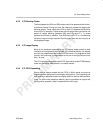
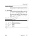
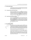
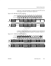
4.5.1 Horizontal Ancillary (HANC) Data Display
HANC data can be displayed using the normal video display mechanism by
programming IMGHSIZEn to occur prior to the SAV code. The HANC data
including the ancillary data header must be part of the YCbCr separated data
in the FIFOs. The VCTHRLD value and DMA size must be programmed to
comprehend the additional samples. You must disable scaling and chroma re-
sampling when including the display of HANC data to prevent data corruption.
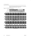
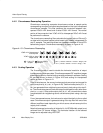
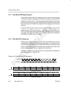
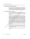
4.5.2 Vertical Ancillary (VANC) Data Display
VANC (or VBI) data is commonly used for such features as teletext and closed-
captioning. No special provisions are made for the display of VBI data. VBI
data may be displayed using the normal display mechanism by programming
IMGVOFF to occur before the first line of active video on the first line of desired
VBI data. Note that the VBI data must be YCbCr separated. You must disable
scaling and chroma resampling when the display of VBI data is desired or the
data will be corrupted by the filters.
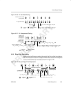
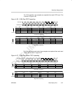
4.6 Raw Data Display Mode
The raw data display modes are intended to output data to a RAMDAC or other
D/A-type device. This is typically RGB formatted data. No timing information
is inserted into the output data stream; instead, selectable control signals are
output to indicate timing. Raw data display includes a synchronized dual channel
option. This allows channel B to output a separate data stream using the same
clock and control as channel A. This mode is useful when used with a second
video port in systems that require 24-bit to 30-bit RGB output.
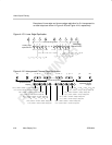
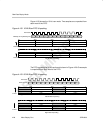
The raw data mode uses a single FIFO of 5120 bytes for storage of output data.
The FIFO is filled by DMAs writing to the Y FIFO destination register A
(YDSTA). DMAs are requested using the YEVTA event. In raw sync mode
(RSYNC bit is set), the FIFO is split into 2560-byte channel A and B buffers.
The channel B FIFO is filled by DMAs using the Y FIFO destination register
B (YDSTB) as a destination. Both YEVTA and YEVTB events are generated
using the channel A timing control.
Ancillary Data Display / Raw Data Display Mode