


Video Port
1-3OverviewSPRU629
-
TSI capture mode: Transport stream interface (TSI) from a front-end
device such as demodulator or forward error correction device in 8-bit
parallel format at up to 30 Mbytes/sec.
- The port generates up to three events per channel and one interrupt to the
DSP.
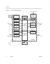
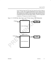
A high-level block diagram of the video port is shown in Figure 1–1. The port
consists of two channels: A and B. A 5120-byte capture/display buffer is split-
table between the two channels. The entire port (both channels) is always
configured for either video capture or display only. Separate data pipelines
control the parsing and formatting of video capture or display data for each of
the BT.656, Y/C, raw video, and TSI modes.
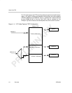
For video capture operation, the video port may operate as two 8/10-bit chan-
nels of BT.656 or raw video capture; or as a single channel of 8/10-bit BT.656,
8/10-bit raw video, 16/20-bit Y/C video, 16/20-bit raw video, or 8-bit TSI.
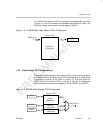
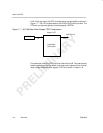
For video display operation, the video port may operate as a single channel
of 8/10-bit BT.656, 8/10-bit raw video, 16/20 bit Y/C video, or 16/20-bit raw
video. It may also operate in a two channel 8/10-bit raw mode in which the two
channels are locked to the same timing. Channel B is not used during single
channel operation.
This document describes the full feature set offered by a 20-bit video port
implementation. Some devices may offer a subset of features such as video
capture only or video display only. Also, some devices may limit the video port
width to 8 or 10 bits. In this case, modes requiring wider video port widths such
as 16-bit raw, 20-bit raw, and Y/C are not supported. See the device-specific
datasheet for details and for I/O timing information.