


Video Capture Registers
3-65Video Capture PortSPRU629
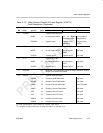
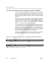
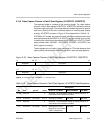
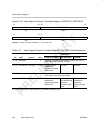
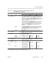
3.13.8 Video Capture Channel x Threshold Register (VCATHRLD, VCBTHRLD)
The video capture channel x threshold register (VCATHRLD, VCBTHRLD)
determines when DMA requests are sent. VCxTHRLD is shown in
Figure 3–36 and described in Table 3–21.
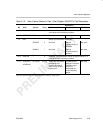
The VCTHRLD1 bits determine when capture DMA events are generated.
Once the threshold is reached, generation of further DMA events is disabled
until service of the previous event(s) begins (the first FIFO read by the DMA
occurs).
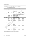
In BT.656 and Y/C modes, every two captured pixels represent 2 luma values
in the Y FIFO and 2 chroma values (1 each in the Cb and Cr FIFOs). Depend-
ing on the data size and packing mode, each value may be a byte (8-bit BT.656
or Y/C), half-word (10-bit BT.656 or Y/C), or subword (dense pack 10-bit
BT.656 or Y/C) within the FIFOs. Therefore, the VCTHRLD1 doubleword
number represents 8 pixels in 8-bit modes, 4 pixels in 10-bit modes, or 6 pixels
in dense pack 10-bit modes. Since the Cb and Cr FIFO thresholds are repre-
sented by ½ VCTHRLD1, certain restrictions are placed on what VCTHRLD1
values are valid (see section 2.3.3).
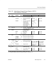
In raw data mode, each data sample may occupy a byte (8-bit raw mode), half-
word (10-bit or 16-bit raw mode), subword (dense pack 10-bit raw mode), or
word (20-bit raw mode) within the FIFO, depending on the data size and pack-
ing mode. Therefore, the VCTHRLD1 doubleword number represents 8 sam-
ples, 4, samples, 6 samples, or 2 samples, respectively.
In TSI mode, VCTHRLD1 represents groups of 8 samples with each sample
occupying a byte in the FIFO.
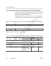
The VCTHRLD2 bits behave identically to VCTHRLD1, but are used during
field 2 capture. It is only used if the field 2 DMA size needs to be different from
the field 1 DMA size for some reason (for example, different captured line
lengths in field 1 and field 2). If VT2EN is not set, then the VCTHRLD1 value
is used for both fields.
Note that the VCTHRLDn applies to data being written into the FIFO. In the
case of 8-bit BT.656 or Y/C modes, this means the output of any selected filter.