


Y/C Video Display Mode
Video Display Port4-16 SPRU629
4.3 Y/C Video Display Mode
The Y/C display mode is similar to the BT.656 display mode but outputs 8 or
10-bit data on separate luma and chroma data streams. One data stream
contains Y samples and the other stream contains multiplexed Cb and Cr
samples co-sited with every other luminance sample. The Y samples are read
from the Y FIFO and the Cb and Cr samples are read from the Cb and Cr FIFOs
and combined on the chroma output. The unpacking and order of the samples
is determined by the sample size (8-bit or 10-bit) and the device endian mode.
The Y/C display mode can generate HDTV standard output such as BT.1120,
SMPTE260, or SMPTE296 with embedded EAV and SAV codes. It can also
output separate control signals.
Because 16 or 20 bits are used for data output, the Y/C output mode requires
both halves of the video port data bus. If the DCHDIS bit in VPCTL is set, then
Y/C mode cannot be selected.
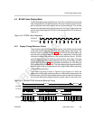
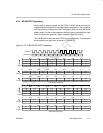
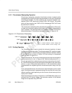
4.3.1 Y/C Display Timing Reference Codes
The EAV and SAV embedded timing codes are identical to those output in
BT.656 mode and timing is controlled in the same manner. In Y/C mode, how-
ever, the codes must be output on both the Y and C data streams
(VDOUT[9–0] and VDOUT[19–10]). An example of BT.1120 line timing is
shown in Figure 4–15.
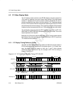
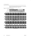
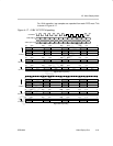
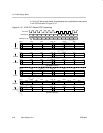
Figure 4–15. Y/C Horizontal Blanking Timing (BT.1120 60I)
VDOUT[9–0]
80.0
80.0
80.0
FF.C
00.0
00.0
Y 0
Y 5
Y 1916
Y 1917
Y 1918
Y 1919
Y 1
Y 2
Y 3
Y 4
One Line
XY.0
80.0
10.0
10.0
FF.C
00.0
00.0
XY.0
80.0
80.0
80.0
FF.C
00.0
00.0
XY.0
80.0
FPCOUNT
SAVEAV Blanking Data EAV
Active VideoBlanking
VCLKOUT
Next Line
4
4
272 1920
VDOUT[19–10]
10.0
10.0
10.0
FF.C
00.0
00.0
Cb 0
Cr 2
Cb 958
Cr 958
Cb 959
Cr 959
Cr 0
Cb 1
Cr 1
Cb 2
XY.0
10.0
80.0
80.0
FF.C
00.0
00.0
XY.0
10.0
10.0
10.0
FF.C
00.0
00.0
XY.0
10.0
SAVEAV Blanking Data EAV
0
5
1916
1917
1918
1920
1
2
3
4
1921
1922
1923
1924
1925
1926
1927
1919
1920
1921
1922
1923
1924
1925
1926
2195
2196
2197
2198
2199
2194
1927