


Video Port Control Registers
2-19Video PortSPRU629
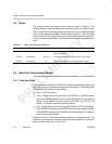
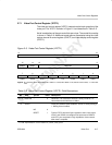
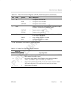
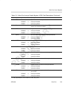
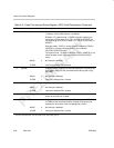
Table 2–5. Video Port Control Register (VPCTL) Field Descriptions (Continued)
Bit DescriptionValuesymval
†
field
†
2 TSI TSI capture mode select bit.
NONE 0 TSI capture mode is disabled.
CAPTURE 1 TSI capture mode is enabled.
1
DISP Display mode select bit. VDATA pins are configured for output.
VCLK2 pin is configured as VCLKOUT output.
CAPTURE 0 Capture mode is enabled.
DISPLAY 1 Display mode is enabled.
0
DCHNL Dual channel operation select bit. If the DCDIS bit in VPSTAT
is set, this bit is forced to 0.
SINGLE 0 Single-channel operation is enabled.
DUAL 1 Dual-channel operation is enabled.
†
For CSL implementation, use the notation VP_VPCTL_field_symval
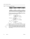
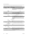
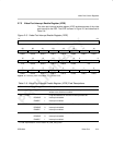
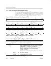
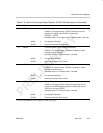
Table 2–6. Video Port Operating Mode Selection
VPCTL Bit
TSI DISP DCHNL Operating Mode
0
0 0 Single channel video capture. BT.656, Y/C or raw mode as selected in VCACTL.
Video capture B channel not used.
0 0 1 Dual channel video capture. Either BT.656 or raw 8/10-bit as selected in
VCACTL and VCBCTL. Option is available only if DCDIS is 0.
0 1 x Single channel video display. BT.656, Y/C or raw mode as selected in VDCTL.
Video display B channel is only used for dual channel sync raw mode.
1
x x Single channel TSI capture.