


Display Timing Examples
4-35Video Display PortSPRU629
4.9 Display Timing Examples
The following are examples of display output for several modes of operation.
4.9.1 Interlaced BT.656 Timing Example
This section shows an example of BT.656 display output for a 704 × 408 inter-
laced output image as might be generated by MPEG decoding.
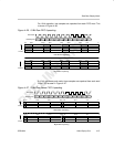
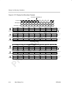
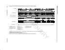
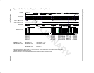
The horizontal output timing is shown in Figure 4–33. This diagram assumes
that there is a two VCLK pipeline delay between the internal counter changing
and the output on external pins. The actual delay can be longer or shorter as
long as it is consistent within any display mode. The BT.656 active line is
720-pixels wide. Figure 4–33 shows the 704-pixel image window centered in
the screen that results in an IMGHOFFx of 8 pixels.
The HBLNK and HSYNC signals are shown as they would be output for active-
low operation. Note that only one of the two signals is actually available exter-
nally. The HBLNK inactive edge occurs either on sample 856 coincident with
the start of SAV or on sample 0 (after SAV) if the HBDLA bit is set. For true
BT.656 operation, neither HBLNK nor HSYNC would be used.
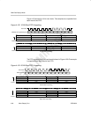
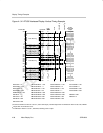
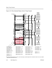
The IPCOUNT operation follows the description in section 4.1.2. IPCOUNT
resets to 0 at the first displayed pixel (FPCOUNT = IMGHOFFx) and stops
counting at the last displayed pixel (IPCOUNT = IMGHSIZEx). The operation
during nondisplay time is not a requirement, it could continue counting until the
next FPCOUNT = IMGHOFFx point or it could reset immediately after
IMGHSIZEx or when FPCOUNT is reset.
VDOUT shows the output data and switching between EAV, Blanking Data,
SAV, Default Data, and FIFO Data. It is assumed that the DVEN bit in VDCTL
is set to enable the default output.