


Raw Data Capture Mode
Video Capture Port3-32 SPRU629
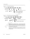
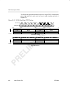
3.7 Raw Data Capture Mode
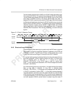
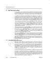
In the raw data capture mode, the data is sampled by the interface only when
the CAPEN signal is active. Data is captured at the rate of the sender’s clock,
without any interpretation or start/stop of capture based on the data values.
To ensure initial capture synchronization to the beginning of a frame, an
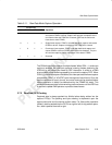
optional setup synchronization enable (SSE) bit is provided in VCxSTRT1. If
the SSE bit is set, then when the VCEN bit is set to 1, the video port will not
start capturing data until after detecting two vertical blanking intervals. If the
SSE bit is cleared to 0, capture begins immediately when the VCEN bit is set.
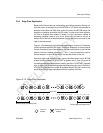
The incoming digital video capture data is stored in the FIFO, which is 2560-bytes
(in dual-channel operation) or 5120-bytes deep (in single-channel operation).
The memory-mapped location YSRCx is associated with the Y buffer. The
YSRCx location is a read-only register and is used to access video data
samples stored in the buffer.
The captured data set size is set by VCxSTOPn. The VCXSTOP and VCYSTOP
bits set the 24-bits of data set size (VCXSTOP sets the lower 12 bits and
VCYSTOP sets the upper 12 bits). Capture is complete and the appropriate
F1C, F2C, or FRMC bit is set when the captured data size reaches the
combined VCYSTOP and VCXSTOP value.
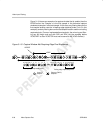
The video port generates a YEVT after the specified number of new samples
has been captured in the buffer. The number of samples required to generate
YEVTx is programmable and is set in the VCTHRLDn bits of VCxTHRLD. On
every YEVT, the DMA should move data from the buffer to the DSP memory.
When moving data from the buffer to the DSP memory, the DMA should use
the YSRCx location as a source address.
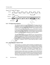
3.7.1 Raw Data Capture Notification
Raw data mode captures a single data packet of information using only
CAPEN for control. Field information is available only for channel A operation
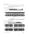
using the FID input on VCTL3. If the RDFE bit in VCACTL is set, then the video
port samples the FID input at the start of each data block (when DCOUNT = 0
and CAPENA is active) to determine the current field. In this case, the CON,
FRAME, CF1, and CF2 bits in VCxCTL are used in a manner identical to
BT.656 mode (see section 3.4.1).
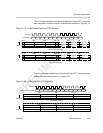
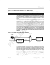
For channel B operation or when the RDFE bit in VCACTL is not set, no field
information is available. Some flexibility in capture and DSP notification is still
provided in order to accommodate various DMA structures and processing
flows. Each raw data packet is treated similar to a progressive scan video
frame. The raw data mode uses the CON and FRAME bits of VCxCTL in a
slightly different manner, as listed in Table 3–11.