


Video Port Control Registers
2-17Video PortSPRU629
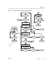
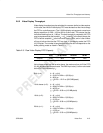
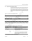
2.7.1 Video Port Control Register (VPCTL)
The video port control register (VPCTL) determines the basic operation of the
video port. The VPCTL is shown in Figure 2–3 and described in Table 2–5.
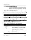
Not all combinations of the port control bits are unique. The control bit encoding
is shown in Table 2–6. Additional mode options are selected using the video
capture channel A control register (VCACTL) and video display control register
(VDCTL).
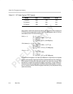
Figure 2–3. Video Port Control Register (VPCTL)
31 16
Reserved
R-0
15 14 13 8
VPRST
VPHLT Reserved
R/WS-0 R/WC-1 R-0
76543210
VCLK2P
VCT3P VCT2P VCT1P Reserved TSI DISP DCHNL
R/W-0 R/W-0 R/W-0 R/W-0 R-0 R/W-0 R/W-0 R/W-0
Legend: R = Read only; R/W = Read/Write; WC = Write a 1 to clear; WS = Write 1 to set, write of 0 has no effect; -n = value after
reset
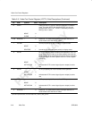
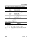
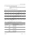
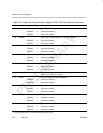
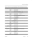
Table 2–5. Video Port Control Register (VPCTL) Field Descriptions
Bit field
†
symval
†
Value Description
31–16 Reserved – 0 Reserved. The reserved bit location is always read as 0. A
value written to this field has no effect.
15 VPRST Video port software reset enable bit. VPRST is set by writing a
1. Writing 0 has no effect.
NO 0
RESET 1 Flush all FIFOs and set all port registers to their initial values.
VCLK1 and VCLK2 are configured as inputs and all VDATA
and VCTL pins are placed in high impedance. Auto-cleared
after reset is complete.
†
For CSL implementation, use the notation VP_VPCTL_field_symval