


GPIO Registers
General Purpose I/O Operation5-8 SPRU629
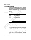
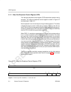
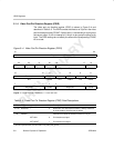
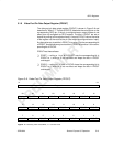
5.1.4 Video Port Pin Direction Register (PDIR)
The video port pin direction register (PDIR) is shown in Figure 5–4 and
described in Table 5–5. The PDIR controls the direction of IO pins in the video
port for those pins set by PFUNC. If a bit is set to 1, the relevant pin or pin group
acts as an output. If a bit is cleared to 0, the pin or pin group functions as an
input. The PDIR settings do not affect pins where the corresponding PFUNC
bit is not set.
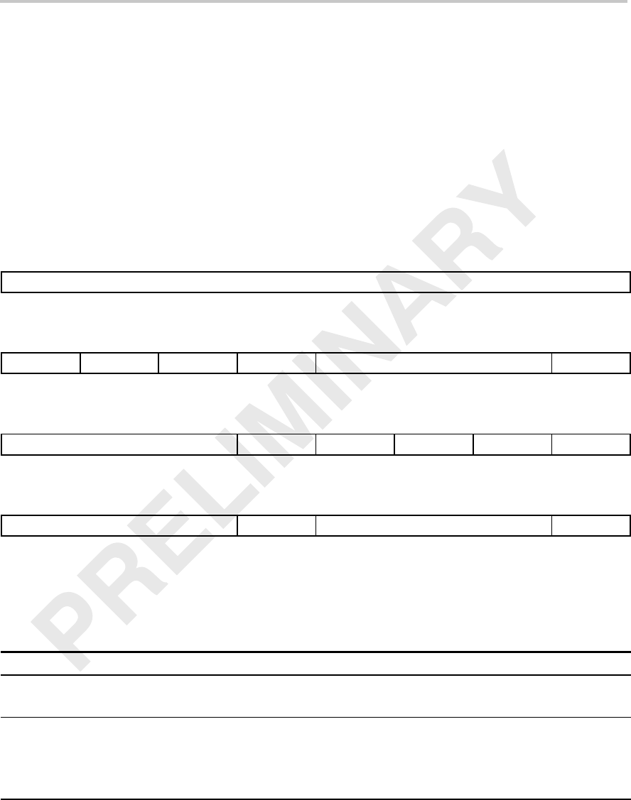
Figure 5–4. Video Port Pin Direction Register (PDIR)
31 24
Reserved
R-0
23 22 21 20 19 17 16
Reserved
PDIR22 PDIR21 PDIR20 Reserved PDIR16
R-0 R/W-0 R/W-0 R/W-0 R-0 R/W-0
15 13 12 11 10 9 8
Reserved
PDIR12 Reserved PDIR10 Reserved PDIR8
R-0 R/W-0 R-0 R/W-0 R-0 R/W-0
754310
Reserved
PDIR4 Reserved PDIR0
R-0 R/W-0 R-0 R/W-0
Legend: R = Read only; R/W = Read/Write; -n = value after reset
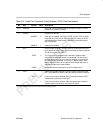
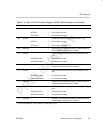
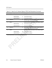
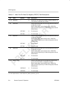
Table 5–5. Video Port Pin Direction Register (PDIR) Field Descriptions
Bit field
†
symval
†
Value Description
31–23 Reserved – 0 Reserved. The reserved bit location is always read as 0.
A value written to this field has no effect.
22 PDIR22 PDIR22 bit controls the direction of the VCTL3 pin.
VCTL3IN 0 Pin functions as input.
VCTL3OUT 1 Pin functions as output.
†
For CSL implementation, use the notation VP_PDIR_field_symval