


Video Capture Registers
Video Capture Port3-72 SPRU629
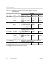
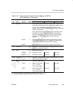
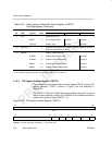
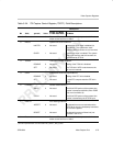
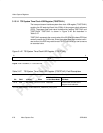
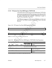
Table 3–23. Video Capture Channel B Control Register (VCBCTL)
Field Descriptions (Continued)
Description
Bit TSI ModeRaw Data ModeBT.656 or Y/C ModeValuesymval
†
field
†
4 CF1
‡
Capture field 1 bit.
NONE 0 Do not capture field 1. Not used. Not used.
FLDCAP 1 Capture field 1. Not used. Not used.
3–2 Reserved – 0 Reserved. The reserved bit location is always read as 0. A value
written to this field has no effect.
1–0 CMODE Capture mode select bit.
BT656B 0 Enables 8-bit BT.656 mode. Not used.
BT656D 1h Enables 10-bit BT.656 mode. Not used.
RAWB 2h Enables 8-bit raw data mode. Not used.
RAWD 3h Enables 10-bit raw data mode. Not used.
†
For CSL implementation, use the notation VP_VCBCTL_field_symval
‡
For complete encoding of these bits, see Table 3–6, Table 3–11, and Table 3–12.
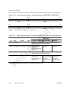
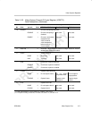
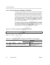
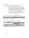
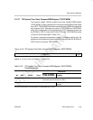
3.13.11 TSI Capture Control Register (TSICTL)
The transport stream interface capture control register (TSICTL) controls TSI
capture operation. TSICTL is shown in Figure 3–39 and described in
Table 3–24.
The ERRFILT, STEN, and TCKEN bits may be written at any time. To ensure
stable counter operation, writes to the CTMODE bit are disabled unless the
system time counter is halted (ENSTC = 0).
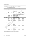
Figure 3–39. TSI Capture Control Register (TSICTL)
31 16
Reserved
R-0
15 6 5 4 3 2 1 0
Reserved
ENSTC TCKEN STEN CTMODE ERRFILT —
R-0 R/W-0 R/W-0 R/W-0 R/W-0 R/W-0 R-0
Legend: R = Read only; R/W = Read/Write; -n = value after reset