


Displaying Video in Raw Data Mode
4-49Video Display PortSPRU629
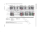
22) If continuous display is enabled, the video port begins displaying again at
the start of the next field or frame. If noncontinuous field 1 and field 2 or
frame display is enabled, the next field or frame is displayed, during which
the DSP must clear the appropriate completion status bit or a DCNA
interrupt occurs and incorrect data may be output.
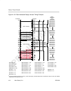
4.11 Displaying Video in Raw Data Mode
In order to display video in the raw data mode, the following steps are needed:
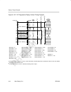
1) Set the frame size in VDFRMSZ. Set the number of lines per frame
(FRMHIGHT) and the number of pixels per line (FRMWIDTH).
2) Set the horizontal blanking in VDHBLNK. Specify the frame pixel counter
value where horizontal blanking starts (HBLNKSTART) and pixel location
where horizontal blanking stops (HBLNKSTOP).
3) Set the vertical blanking start for field 1 in VDVBLKS1. Specify the frame
line (VBLNKYSTART1) and frame pixel counter (VBLNKXSTART1) values
for the pixel where vertical blanking starts for field 1.
4) Set the vertical blanking end for field 1 in VDVBLKE1. Specify the frame
line (VBLNKYSTOP1) and frame pixel counter (VBLNKXSTOP1) values
for the pixel where vertical blanking ends for field 1.
5) Set the vertical blanking start for field 2 in VDVBLKS2. Specify the frame
line (VBLNKYSTART2) and frame pixel counter (VBLNKXSTART2) values
for the pixel where vertical blanking starts for field 2.
6) Set the vertical blanking end for field 2 in VDVBLKE2. Specify the frame
line (VBLNKYSTOP2) and frame pixel counter (VBLNKXSTOP2) values
for the pixel where vertical blanking ends for field 2.
7) Set the vertical synchronization start for field 1 in VDVSYNS1. Specify the
frame line (VSYNCYSTART1) and frame pixel counter (VSYNCXSTART1)
values for the pixel where vertical synchronization starts for field 1.
8) Set the vertical synchronization end for field 1 in VDVSYNE1. Specify the
frame line (VSYNCYSTOP1) and frame pixel counter (VSYNCXSTOP1)
values for the pixel where vertical synchronization ends for field 1.
9) Set the vertical synchronization start for field 2 in VDVSYNS2. Specify the
frame line (VSYNCYSTART2) and frame pixel counter (VSYNCXSTART2)
values for the pixel where vertical synchronization starts for field 2.
10) Set the vertical synchronization end for field 2 in VDVSYNE2. Specify the
frame line (VSYNCYSTOP2) and frame pixel counter (VSYNCXSTOP2)
values for the pixel where vertical synchronization ends for field 2.