


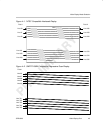
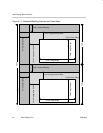
Video Capture Registers
Video Capture Port3-82 SPRU629
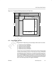
3.13.20 TSI System Time Clock Ticks Interrupt Register (TSITICKS)
The transport stream interface system time clock ticks interrupt register
(TSITICKS) is used to generate an interrupt after a certain number of ticks of
the 27-MHz system time clock. When the TICKCT value is set to X and the
TCKEN bit in TSICTL is set, the TICK bit in VPIS is set every X + 1 STCLK
cycles. Note that the tick interrupt counter and comparison logic function are
separate from the PCR logic and always count STCLK cycles regardless of the
value of the CTMODE bit in TSICTL. TSITICKS is shown in Figure 3–48 and
described in Table 3–33.
A write to TSITICKS resets the tick counter 0. Whenever the tick counter
reaches the TICKCT value, the TICK bit in VPIS is set and the counter resets
to 0.
To prevent inaccurate comparisons caused by changing register bits, the soft-
ware should disable the tick count interrupt (clear the TCKEN bit in TSICTL)
prior to writing to TSITICKS.
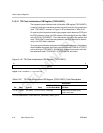
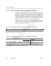
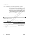
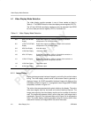
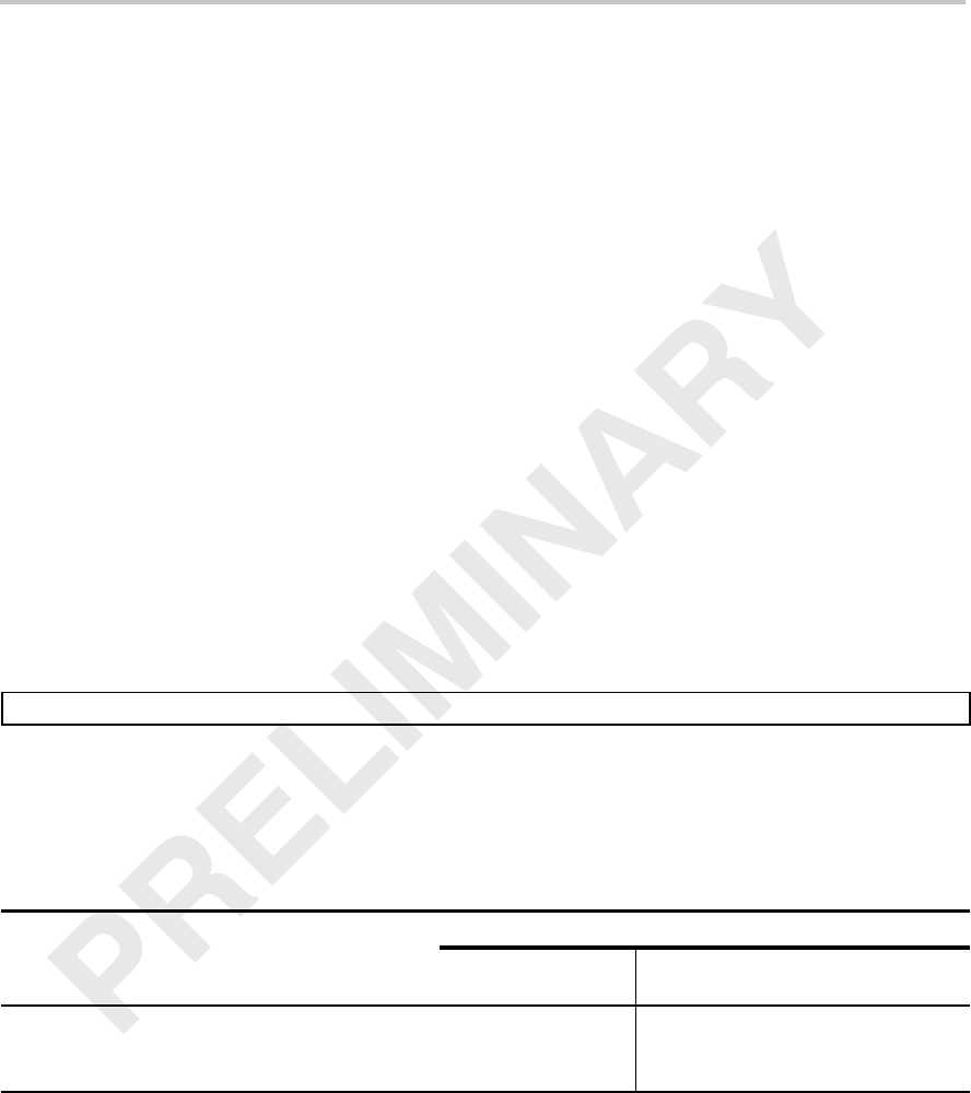
Figure 3–48. TSI System Time Clock Ticks Interrupt Register (TSITICKS)
31 0
TICKCT
R/W-0
Legend: R/W = Read/Write; -n = value after reset
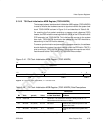
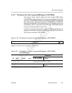
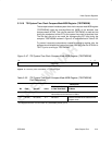
Table 3–33.TSI System Time Clock Ticks Interrupt Register (TSITICKS) Field Descriptions
Description
Bit Field symval
†
Value
BT.656, Y/C Mode,
or Raw Data Mode
TSI Mode
31–0 TICKCT OF(value) 0–FFFF FFFFh Not used. Contains the number of ticks of the
27-MHz system time clock required
to generate a tick count interrupt.
†
For CSL implementation, use the notation VP_TSITICKS_TICKCT_symval