


Video Display Registers
Video Display Port4-88 SPRU629
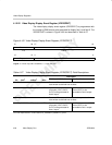
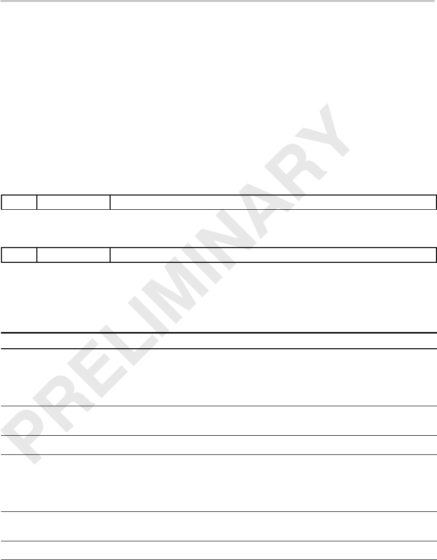
4.12.25 Video Display Vertical Interrupt Register (VDVINT)
The video display vertical interrupt register (VDVINT) controls the generation
of vertical interrupts in field 1 and field 2. The VDVINT is shown in Figure 4–64
and described in Table 4–30.
An interrupt can be generated upon completion of the specified line in a field
(when FLCOUNT = VINTn). This allows the software to synchronize itself to
the frame or field. The interrupt can be programmed to occur in one, both, or
no fields using the VIF1 and VIF2 bits.
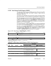
Figure 4–64. Video Display Vertical Interrupt Register (VDVINT)
31 30 28 27 16
VIF2
Reserved VINT2
R/W-0 R-0 R/W-0
15 14 12 11 0
VIF1
Reserved VINT1
R/W-0 R-0 R/W-0
Legend: R = Read only; R/W = Read/Write; -n = value after reset
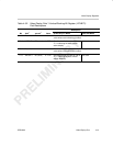
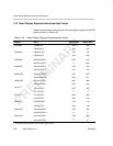
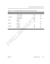
Table 4–30. Video Display Vertical Interrupt Register (VDVINT) Field Descriptions
Bit field
†
symval
†
Value Description
31 VIF2 Vertical interrupt (VINT) in field 2 enable bit.
DISABLE 0 Vertical interrupt (VINT) in field 2 is disabled.
ENABLE 1 Vertical interrupt (VINT) in field 2 is enabled.
30–28
Reserved – 0 Reserved. The reserved bit location is always read as 0. A
value written to this field has no effect.
27–16 VINT2 OF(value) 0–FFFh Line where vertical interrupt (VINT) occurs, if VIF2 bit is set.
15 VIF1 Vertical interrupt (VINT) in field 1 enable bit.
DISABLE 0 Vertical interrupt (VINT) in field 1 is disabled.
ENABLE 1 Vertical interrupt (VINT) in field 1 is enabled.
14–12
Reserved – 0 Reserved. The reserved bit location is always read as 0. A
value written to this field has no effect.
11–0 VINT1 OF(value) 0–FFFh Line where vertical interrupt (VINT) occurs, if VIF1 bit is set.
†
For CSL implementation, use the notation VP_VDVINT_field_symval