


Reset Operation
Video Port2-2 SPRU629
2.1 Reset Operation
The video port has several sources and types of resets. The actions performed
by these resets and the state of the port following the resets is described in the
following sections.
2.1.1 Power-On Reset
Power-on reset is an asynchronous hardware reset caused by a chip-level
reset operation. The reset is initiated by a power-on reset input to the video
port. When the input is active, the port places all I/Os (VD[19–0], VCTL1,
VCTL2, VCTL3, and VCLK2) in a high-impedance state.
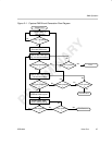
2.1.2 Peripheral Bus Reset
Peripheral bus reset is a synchronous hardware reset caused by a chip-level
reset operation. The reset is initiated by a peripheral bus reset input to the video
port. This reset can be used internally (continuously asserted) to disable the
video port for low-power operation. When the input is active, the port does the
following:
- Places (keeps) all I/Os (VD[19–0], VCTL1, VCTL2, VCTL3, and VCLK2)
in a high-impedance state.
- Flushes the FIFOs (resets pointers)
- Resets all port, capture, display, and GPIO registers to their default
values. These may not complete until the appropriate module clock
(VCLK1, VCLK2, STCLK) edges occur to synchronously release the logic
from reset.
- Clears PEREN bit in PCR to 0.
- Sets VPHLT bit in VPCTL to 1.
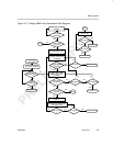
While the peripheral remains disabled (PEREN = 0):
- VCLK1, VCLK2, and STCLK are gated off to save peripheral power.
- Peripheral bus accesses are acknowledged (RREADY/WREADY
returned) to prevent DMA lock-up. (Any value returned on reads, data
accepted or discarded on writes.)
- Peripheral bus MMR interface allows access to GPIO registers only (PID,
PCR, PFUNC, PDIR, PIN, PDOUT, PDSET, PDCLR, PIEN, PIPOL,
PISTAT, and PICLR).
- Port I/Os (VD[19–0], VCTL1, VCTL2, VCTL3, and VCLK2) remain in a
high-impedance state unless enabled as GPIO by the PFUNC bits.