


Video Capture Registers
3-73Video Capture PortSPRU629
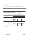
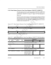
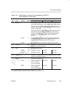
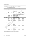
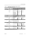
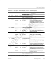
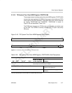
Table 3–24. TSI Capture Control Register (TSICTL) Field Descriptions
Description
Bit field
†
symval
†
Value
BT.656, Y/C Mode,
or Raw Data Mode
TSI Mode
31–6 Reserved – 0 Reserved. The reserved bit location is always read as 0. A value
written to this field has no effect.
5 ENSTC System time clock enable bit.
HALTED 0 Not used. System time clock input is disabled (to
save power). The system time clock
counters and tick counter do not increment.
CLKED 1 Not used. System time input is enabled. The system
time clock counters and tick counters are
incremented by STCLK.
4 TCKEN Tick count interrupt enable bit.
DISABLE 0 Not used. Setting of the TICK bit is disabled.
SET 1 Not used. The TICK bit in VPIS is set whenever the
tick count is reached.
3 STEN System time clock interrupt enable bit.
DISABLE 0 Not used. Setting of the STC bit is disabled.
SET 1 Not used. A valid STC compare sets the STC bit in
VPIS.
2 CTMODE Counter mode select bit.
90KHZ 0 Not used. The 33-bit PCR portion of the system time
counter increments at 90 kHz (when PCRE
rolls over from 299 to 0).
STCLK 1 Not used. The 33-bit PCR portion of the system time
counter increments by the STCLK input.
1 ERRFILT Error filtering enable bit.
ACCEPT 0 Not used. Packets with errors are received and the
PERR bit is set in the timestamp inserted at
the end of the packet.
REJECT 1 Not used. Packets with errors are filtered out (not
received in the FIFO).
0 Reserved – 0 Reserved. The reserved bit location is always read as 0. A value
written to this field has no effect.
†
For CSL implementation, use the notation VP_TSICTL_field_symval