


Video Port Control Registers
2-27Video PortSPRU629
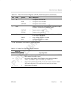
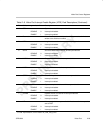
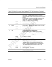
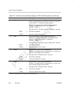
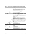
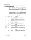
Table 2–9. Video Port Interrupt Status Register (VPIS) Field Descriptions (Continued)
Bit DescriptionValuesymvalfield
13 DCMP Display complete. Indicates that the entire frame has been driven
out of the port. The DMA complete interrupt can be used to
determine when the last data has been transferred from memory to
the FIFO.
DCMP is set after displaying an entire field or frame (when F1D,
F2D or FRMD in VDSTAT are set) depending on the CON,
FRAME, DF1, and DF2 control bits in VDCTL.
NONE 0 No interrupt is detected.
CLEAR 1 Interrupt is detected. Bit is cleared.
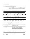
12
DUND Display underrun. Indicates that the display FIFO ran out of data.
NONE 0 No interrupt is detected.
CLEAR 1 Interrupt is detected. Bit is cleared.
11
TICK System time clock tick interrupt detected bit.
BT.656, Y/C capture mode or raw data mode – Not used.
TSI capture mode –TICK is set when the TCKEN bit in TSICTL is
set and the desired number of system time clock ticks has
occurred as programmed in TSITICKS.
NONE 0 No interrupt is detected.
CLEAR 1 Interrupt is detected. Bit is cleared.
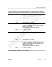
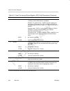
10
STC System time clock interrupt detected bit.
BT.656, Y/C capture mode or raw data mode – Not used.
TSI capture mode – STC is set when the system time clock
reaches an absolute time as programmed in TSISTCMPL and
TSISTCMPM registers and the STEN bit in TSICTL is set.
NONE 0 No interrupt is detected.
CLEAR 1 Interrupt is detected. Bit is cleared.
9–8
Reserved – 0 Reserved. The reserved bit location is always read as 0. A value
written to this field has no effect.
†
For CSL implementation, use the notation VP_VPIS_field_symval