


Video Port FIFO
1-9OverviewSPRU629
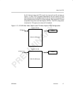
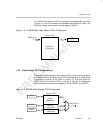
For 16/20-bit raw video, the FIFO is configured as a single buffer, as shown
in Figure 1–5. The FIFO receives 16/20-bit data from the VDIN[19–0] bus. The
FIFO has a single write pointer and read register (YSRCA).
Figure 1–5. 16/20-Bit Raw Video Capture FIFO Configuration
Data Buffer
(5120 bytes)
VDIN[19–0]
16/20
Capture FIFO
YSRCA
64
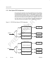
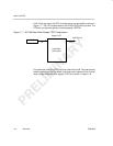
1.2.3 Video Display FIFO Configurations
During video display operation, the video port FIFO has one of five configura-
tions depending on the display mode. For BT.656 operation, a single output
is provided on channel A, as shown in Figure 1–6, with data output on
VDOUT[9–0]. The channel’s FIFO is split into Y, Cb, and Cr buffers with
separate read pointers and write registers (YDSTA, CBDST, and CRDST).
Figure 1–6. BT.656 Video Display FIFO Configuration
Y Buffer
(2560 bytes)
Cb Buffer
(1280 bytes)
Cr Buffer
(1280 bytes)
YDSTA
CBDST
CRDST
VDOUT[9–0]
Display FIFO
8/10
8/10
8/10
64
64
64