


VIC Port Registers
6-9VCXO Interpolated Control PortSPRU629
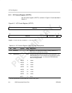
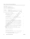
6.5.3 VIC Clock Divider Register (VICDIV)
The VIC clock divider register (VICDIV) defines the clock divider for the VIC
interpolation frequency. The VIC interpolation frequency is obtained by divid-
ing the module clock. The divider value written to VICDIV is:
Divider + Round
ƪ
DCLK
ń
R
]
where DCLK is the CPU clock divided by 2, and R is the desired interpolation
frequency. The interpolation frequency depends on precision β.
The default value of VICDIV is 0001h; 0000h is an illegal value. The VIC module
uses a value of 0001h whenever 0000h is written to this register.
The DSP can write to VICDIV only when the GO bit in VICCTL is cleared to 0.
If a write is performed when the GO bit is set to 1, the VICDIV bits remain
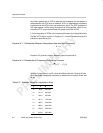
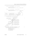
unchanged. The VICDIV is shown in Figure 6–5 and described in Table 6–6.
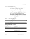
Figure 6–5. VIC Clock Divider Register (VICDIV)
31 16
Reserved
R-0
15 0
VICCLKDIV
R/W-0001h
Legend: R = Read only; R/W = Read/Write; -n = value after reset
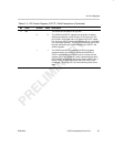
Table 6–6. VIC Clock Divider Register (VICDIV) Field Descriptions
Bit Field symval
†
Value Description
31–16 Reserved – 0 Reserved. The reserved bit location is always read as 0. A
value written to this field has no effect.
15–0 VICCLKDIV OF(value) 0–FFFFh The VIC clock divider bits define the clock divider for the
VIC interpolation frequency.
†
For CSL implementation, use the notation VIC_VICDIV_VICCLKDIV_symval