


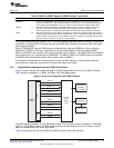
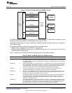
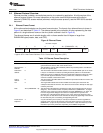
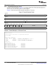
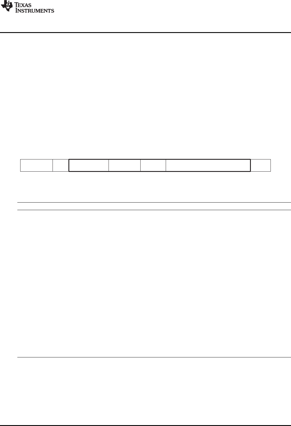
Preamble
SFD
Destination
Source
Len Data
7 1 6 6 2 46 − (RXMAXLEN - 18) 4
FCS
Number of bytes
Legend: SFD = Start Frame Delimiter; FCS = Frame Check Sequence (CRC)
www.ti.com
EMAC Functional Architecture
2.4 Ethernet Protocol Overview
Ethernet provides a reliable, connectionless service to a networking application. A brief overview of the
ethernet protocol follows. For more information on the carrier sense multiple access with collision
detection (CSMA/CD) access method (ethernet's multiple access protocol), see the IEEE 802.3 standard
document.
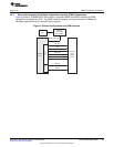
2.4.1 Ethernet Frame Format
All the ethernet technologies use the same frame structure. The format of an ethernet frame is shown in
Figure 9 and described in Table 12. The ethernet packet is the collection of bytes representing the data
portion of a single ethernet frame on the wire (shown outlined in bold in Figure 9).
The ethernet frames are of variable lengths, with no frame smaller than 64 bytes or larger than
RXMAXLEN bytes (header, data, and CRC).
Figure 9. Ethernet Frame
Table 12. Ethernet Frame Description
Field Bytes Description
Preamble 7 These 7 bytes have a fixed value of 55h. They wake up the receiving EMAC ports and
synchronize their clocks to that of the sender's clock.
Start-of-Frame 1 This field with a value of 5Dh immediately follows the preamble pattern and indicates
Delimiter the start of important data.
Destination 6 This field contains the Ethernet MAC address of the intended EMAC port for the frame.
address It may be an individual or multicast (including broadcast) address. If the destination
EMAC port receives an Ethernet frame with a destination address that does not match
any of its MAC physical addresses, and no promiscuous, multicast or broadcast
channel is enabled, it discards the frame.
Source 6 This field contains the MAC address of the Ethernet port that transmits the frame to the
address Local Area Network.
Len 2 The length field indicates the number of EMAC client data bytes contained in the
subsequent data field of the frame. This field can also be used to identify the data type
carried by the frame.
Data 46 to (RXMAXLEN - 18) This field carries the datagram containing the upper layer protocol frame (the IP layer
datagram). The maximum transfer unit (MTU) of Ethernet is (RXMAXLEN - 18) bytes.
Therefore, if the upper layer protocol datagram exceeds (RXMAXLEN - 18) bytes, the
host must fragment the datagram and send it in multiple Ethernet packets. The
minimum size of the data field is 46 bytes. Thus, if the upper layer datagram is less
then 46 bytes, the data field must be extended to 46 bytes by appending extra bits after
the data field, but prior to calculating and appending the FCS.
Frame Check 4 A cyclic redundancy check (CRC) is used by the transmit and receive algorithms to
Sequence generate a CRC value for the FCS field. The frame check sequence covers the 60 to
(RXMAXLEN - 4) bytes of the packet data. Note that the 4-byte FCS field may not be
included as part of the packet data, depending on the EMAC configuration.
29
SPRUEF8F–March 2006–Revised November 2010 C6472/TCI6486 EMAC/MDIO
Submit Documentation Feedback
Copyright © 2006–2010, Texas Instruments Incorporated