


Waiting
Count
Output
EVT_PULSE=0(or)EVT_PULSE=1&&
CNT >=CNT_CFG&& TIME_CFGI=0
Increment
CNT
CNT=1
EVT_PULSE=0
&&CR=0
EVT_PULSE=0
&& CR=1
EVT_PULSE=1 &&
CNT < CNT_CFG &&
CR=0
EVT_PULSE=1 &&
CNT < CNT_CFG
CNT=1
NEXT_
DIV=1
CNT=1
EVT_PULSE=1&&
CR=1&&CNT <
CNT_CFG
EVT_PULSE=1 && CNT >=
CNT_CFG && TIME_CFG==0
NEXT_
DIV=1
CNT >=CNT_CFG
&&EVT_PULSE=1
EVT_PULSE=1&&
CNT <CNT_CFG
EVT_PULSE=0 (or)
CNT >= CNT_CFG
EMAC Functional Architecture
www.ti.com
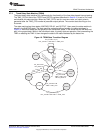
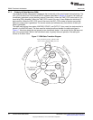
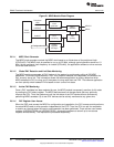
2.7.3 Divide-by-N State Machine (DSM)
The divide-by-N state machine fully implements the functionality of the count-based interrupt pacing. The
CNT_CFG bit field of the TPCFG and RPCFG registers (described in Section 3) is set to 0 on reset and
immediately generates a pulse (basically means a zero delay), when the TIME_CFG is also set to 0 (i.e.,
timed-delay SM is disabled). When the TIME_CFG is set to non-zero, it then disables the divide-by-N
state machine. When the CNT_CFG is set to non-zero, the CNT_CFG number of events are counted
before an output pulse is generated. The counter resets (and reloads) every time when a divide-by-N
pulse is generated.
The state machine has three states, WAITING, COUNT, and OUTPUT. Upon reset, the state machine is
placed in the WAITING state. The state machine makes transitions between the states as shown in
Figure 17. Note that states that are grayed out are transitional states, in the sense that the SM does not
stay in the grayed state. While in the transitional state, it typically does an operation, like setting the
counter to a certain value.
Figure 17. DSM State Transition Diagram
44
C6472/TCI6486 EMAC/MDIO SPRUEF8F–March 2006–Revised November 2010
Submit Documentation Feedback
Copyright © 2006–2010, Texas Instruments Incorporated