


www.ti.com
EMAC Functional Architecture
2.16 Initialization
2.16.1 Enabling the EMAC/MDIO Peripheral
When the device is powered on, the EMAC peripheral is disabled. Prior to EMAC-specific initialization, the
EMAC must be enabled; otherwise its registers cannot be written, and the reads will all return a value of
zero. The interface to be used (MII, RMII, GMII, or RGMII) is automatically selected at power-on reset,
based on the state of the MACSEL configuration pins.
EMAC/MDIO is enabled through the chip level module state control register 0 (MDCTL0) and module
status register 0 (MDSTAT0). For detailed information on the programming sequence, see the
TMS320TCI6486 Communications Infrastructure Digital Signal Processor data manual (SPRS300) or the
TMS320C6472 Fixed-Point Digital Signal Processor data manual (SPRS612). This sequence enables the
EMAC peripheral, and the register values are reset to default. Module-specific initialization may proceed.
2.16.2 EMIC Module Initialization
The EMIC module is used for global interrupt enable, and to pace back-to-back interrupts using an
interrupt re-trigger count based on the peripheral clock (CPUCLK/6).
Note that although the EMIC module and the EMAC module have slightly different functions, in practice,
the type of maintenance performed on the EMIC module is more commonly conducted from the EMAC
module software (as opposed to the MDIO module).
The initialization of the EMIC module consists of two parts:
1. Configuration of the interrupt on the DSP.
2. Initialization of the EMIC module:
• Setting the interrupt pace count delay and prescaler
• Initializing the EMAC and MDIO modules
• Enabling interrupts in the EW_INTCTL
Use the system's interrupt controller to map the EMAC interrupts to one of the CPU's interrupts. Once the
interrupt is mapped to a CPU interrupt, general masking and unmasking of the interrupt (to control
reentrancy) should be done at the chip level by manipulating the interrupt enable mask. The EMIC module
interrupt control register (EW_INTCTL) should only enable and disable interrupts from within the EMAC
interrupt service routine (ISR), as disabling and re-enabling the interrupt in EW_INTCTL also resets the
interrupt pace counter.
2.16.3 MDIO Module Initialization
The MDIO module initially configures and monitors one or more external PHY devices. Other than
initializing the software state machine (details on the MDIO state machine can be found in the IEEE 802.3
standard), the MDIO module only needs the MDIO engine enabled and the clock divider configured. To
set the clock divider, supply an MDIO clock of 1 MHz. As the peripheral clock is used as the base clock
(CPUclk/6), the divider can be set to 125 for a 750 MHz device. Slower MDIO clocks for slower CPU
frequencies are acceptable.
Both the state machine enable and the MDIO clock divider are controlled through the MDIO control
register (CONTROL). If none of the potentially connected PHYs require the access preamble, the
PREAMBLE bit can also be set in CONTROL to speed up PHY register access. See Example 4 for an
example of the code for initialization.
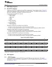
Example 4. MDIO Module Initialization Code
#define PCLK 125
...
/* Enable MDIO and setup divider */
MDIO_REGS->CONTROL = CSL_FMKT( MDIO_CONTROL_ENABLE, YES) |
CSL_FMK( MDIO_CONTROL_CLKDIV, PCLK ) ;
65
SPRUEF8F–March 2006–Revised November 2010 C6472/TCI6486 EMAC/MDIO
Submit Documentation Feedback
Copyright © 2006–2010, Texas Instruments Incorporated