


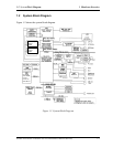

1.2 System Block Diagram 1 Hardware Overview
Chipset
This gate array has the following elements and functions.
• North Bridge (Intel Montara-GML)
− CPU interface and controller
− Host bus support
− System memory SDRAM controller
− Hub interface
− AGP interface
− Power management
− Graphic controller
• South Bridge (Intel ICH4-M)
− LAN controller
− IDE controller
− DMA controller
− USB interface
− SM Bus interface
− Interrupt controller
− Power management
− Firmware Hub interface
− Low Pin count (LPC) interface
− Real time clock
− AC’97 interface
− Audio controller
− Hub interface
PC card controller (YEBISUSS)
− PCI interface (PCI Revision 2.2)
− Deeper Sleep control interface
− Chipset interface
Intel serial interrupt
− Card Bus /PC card controller (Yenta Version 2.2: 1 slot)
Parallel power control (Toshiba style)
− SD memory card controller (SDHC Version 1.2)
− SD IO card controller (Version 1.1)
− Smart Card interface debug port
− Docking station interface
Q Switch control, reset control
− External device interface
FDD/IDE hot plug plug-and-play control
Satellite A10/TECRA A1/Satellite Pro A10 Maintenance Manual (960-445) 1-7