


2 Troubleshooting Procedures 2.8 Display Troubleshooting
2.8 Display Troubleshooting
This section describes how to determine if the computer’s display is functioning properly.
Start with Procedure 1 and continue with the other procedures as instructed.
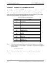
Procedure 1: Diagnostic Test Program Execution Check
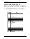
Procedure 2: Connector and Cable Check
Procedure 3: Replacement Check
Procedure 1 Diagnostic Test Program Execution Check
The Display Test program is stored on the Diagnostics disk. Insert the Diagnostics disk in the
computer’s floppy disk drive, turn on the computer and run the test. Refer to Chapter 3, Tests
and Diagnostics for details.
This program checks the display controller on the system board. If an error is detected, go to
Procedure 3.
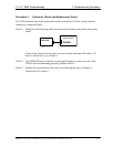
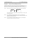
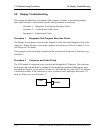
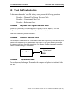
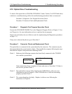
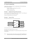
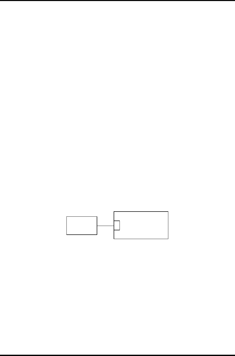
Procedure 2 Connector and Cable Check
The LCD module is connected to the system board through the LCD harness. The cable may
be disconnected from the board or damaged. Disassemble the computer following the steps
described in Chapter 4, Replacement Procedures. Check that the pin of the LCD I/F connector
is not bent or broken. If the connection is loose, reconnect firmly and repeat Procedure 2. If
there is still an error, go to Procedure 3.
LCD
System Board
PJ5600
2-48 Satellite A10/TECRA A1/Satellite Pro A10 Maintenance Manual (960-445)