


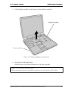

4.13 System Board/DC-IN Jack/RTC Battery 4 Replacement Procedures
Installing the System Board/DC-IN Jack/RTC Battery
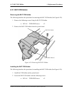
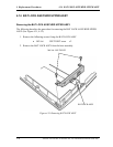
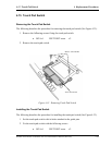
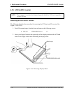
The following describes the procedure for installing the system board/DC-IN Jack/RTC
Battery (See Figure 4-29, 4-30).
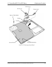
1. Attach the FIR dummy cover on the base assembly. Make sure the latches are setured.
2. Install the modem jack on the base assembly.
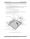
3. Connect the DC-IN jack cable to PJ8800 on the system board.
4. Connect the RTC battery cable to PJ8790 on the system board.
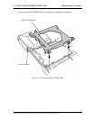
5. Insert the system board into the base assembly from the microphone and headphone
jack side first.
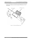
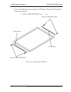
6. Install the DC-IN jack to the base assembly.
7. Insert the RTC battery into the slot on the base assembly.
8. Secure the system board with the following screws.
• M2.5x5 THIN BIND screw x2
Satellite A10/TECRA A1/Satellite Pro A10 Maintenance Manual (960-445) 4-45