


4 Replacement Procedures 4.18 Fluorescent Lamp
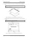
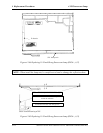
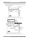
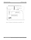
7. Bend the TCP attaching to the source board and secure it with two screws. Then bend
the TCP attaching to the gate board with two screws and insert the FPC (G) into the
connector of the source board.
Do not hold the ed
g
e.Do not hold the ed
g
e.
Figure 4-170 Replacing 15.0 Inch Sharp fluorescent lamp (SXGA+) (18)
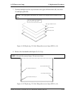
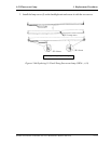
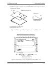
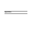
Screw
Screw
Screw
(G)
Fit the pin and the hole.
Screw
Fit the pin and the hole.
Do not cover the
projection.
Fit the pin and the hole.
Fold the gate board.
Screw tightening torque: 0.9kg
•
cm
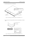
Fold the source board.
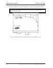
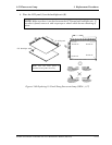
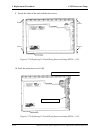
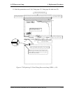
Check the condition after mating.
*Check the condition of the concave portion of
the FPC and the outline of the connector.
*Insert the FPC to the end. There shall be no
out of position in
θ
.
*Lock surely the connector.
Poor mating: Failure
Out-of-position in
θ
: Failure
Figure 4-171 Replacing 15.0 Inch Sharp fluorescent lamp (SXGA+) (19)
4-156 Satellite A10/TECRA A1/Satellite Pro A10 Maintenance Manual (960-445)