


4 Replacement Procedures 4.18 Fluorescent Lamp
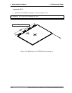
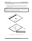
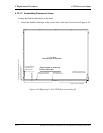
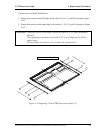
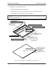
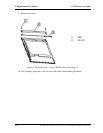
Attaching the tapes and insulation sheet
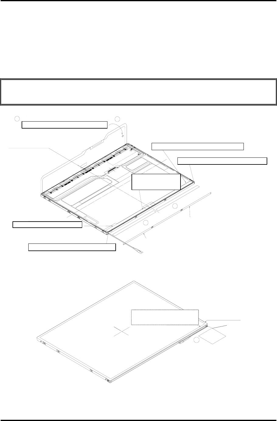
1. Attach the PCB insulation sheet (one point).
2. Attach the tape for the bezel to the bottom area close to the lamp (two points).
3. Attach the tape for fixing the FL tube cable (one point).
CAUTION: When attaching tape and insulation sheet, be careful not to damage the TAB
and lamp cable connections.
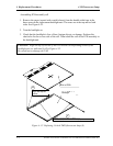
絶縁シートのたわみ無きよう貼り付ける.
2
1
乗り上げて無いこと
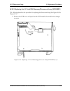
PCBがフレームに
押しながら貼る.
ベゼルが浮かない様,
ベゼルテープ貼り付け
絶縁シート貼り付け
1
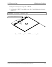
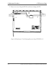
リフレクタ端を目安に貼る
モジュール端を目安に貼る
モジュール端を目安に貼る
モジュール表面に出ないこと
モジュール表面に出ないこと
リフレクタ端を目安に貼る
2
5
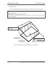
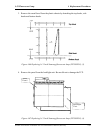
ケーブル引き出し口を覆うこと
ゴムキャップ:
モジュール端を目安に貼る
貼り基準:
ベゼル端から出ないこと
貼り基準:
Att
ac
hi
ng
th
e
i
nsu
l
a
ti
on s
h
ee
t
Att
ac
h
th
e s
h
ee
t
a
ft
er remov
i
ng s
l
ac
k
.
Th
e
f
rame mus
t
no
t
b
e
overlaid with the PCB.
Ali
gn
th
e s
h
ee
t
w
ith
th
e mo
d
u
l
e
'
s e
d
ge.
A
li
g
n the sheet with the reflector's ed
g
e.
Ali
gn
th
e s
h
ee
t
w
ith
th
e re
fl
ec
t
or
'
s e
d
ge.
Ali
gn
th
e s
h
ee
t
w
ith
th
e mo
d
u
l
e
'
s e
d
ge.
Th
e
t
ape e
d
ge mus
t
no
t
protrude from the surface
of the module.
Th
e
t
ape e
d
ge mus
t
no
t
pro
t
ru
d
e
from the surface of the module.
A
ttac
h
t
h
e s
h
eet
by
pressing it so that the
bezel may not "fly".
Att
ac
hi
ng
th
e
t
ape
f
or
th
e
b
eze
l
R
equ
i
remen
t
s
f
or a
tt
ac
h
men
t
:
The tape edge must not go
be
y
ond the bezel's ed
g
e.
R
equ
i
remen
t
s
f
or a
tt
ac
h
men
t
:
The tape edge must not go
beyond the module's edge.
R
u
bb
er cap:
Must cover the
opening for the cable.
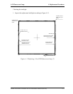
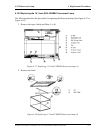
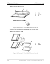
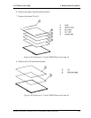
Figure 4-56 Replacing 14 Inch TMD fluorescent lamp (12)
4-76 Satellite A10/TECRA A1/Satellite Pro A10 Maintenance Manual (960-445)