


4 Replacement Procedures 4.18 Fluorescent Lamp
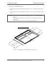
Setting the bezel
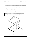
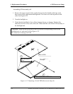
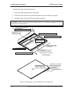
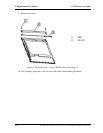
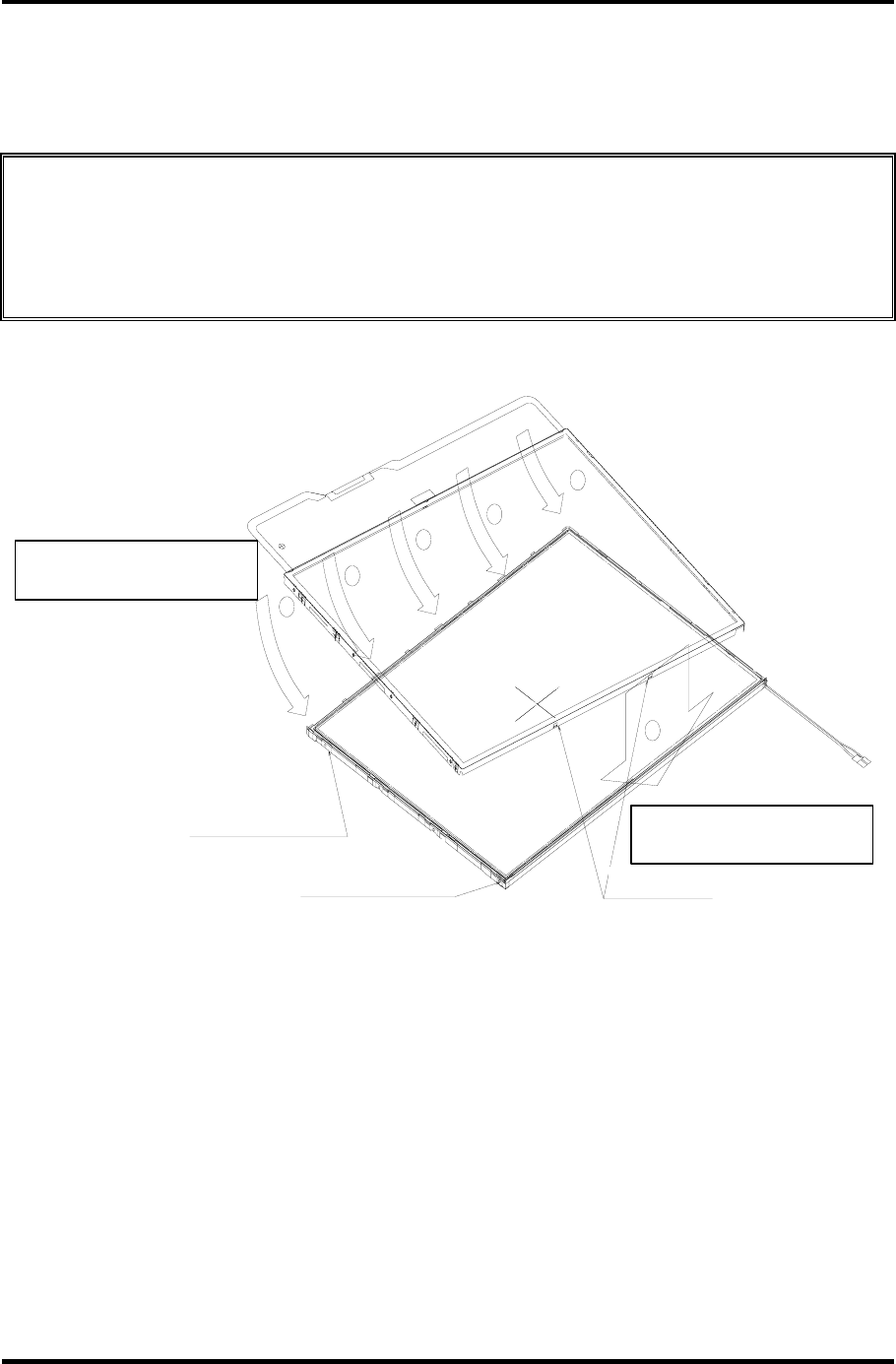
1. Start installing the bezel in the upward direction until it stops at the top left corner.
NOTE: The GND-CU and lamp reflector on the left-hand side must not go beyond the
edges of the bezel.
Be careful not to damage the cables and TAB.
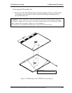
The bezel latches must be engaged (there are five latches on the top edge, and two latches
on the bottom edge).
ラッチ2箇所有り.
ラッチ5か所をはめる.
次にたTAB側をはめる.
ケーブルをキズつけないように注意
ベゼルをランプ側からはめる.
ベゼルの外に出ないこと.
GND-CU折り曲げ有り.
ベゼルの外に出ないこと
リフレクタ折り曲げ有り.
2
2
2
2
2
1
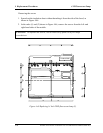
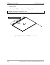
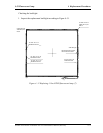
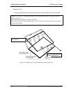
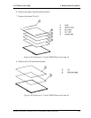
Next, fit the bezel’s edge close to the TAB.
Close the five latches.
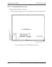
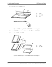
First, fit the bezel’s edge close to the lamp.
Use care not to damage the cable.
The fold of GND-CU must not
go beyond the bezel’s edge.
The fold of reflector must not g
o
beyond the bezel’s edge.
Two latches
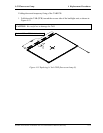
Figure 4-54 Replacing 14 Inch TMD fluorescent lamp (10)
4-74 Satellite A10/TECRA A1/Satellite Pro A10 Maintenance Manual (960-445)