


4 Replacement Procedures 4.18 Fluorescent Lamp
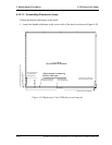
Assembling PCB-assembly cell
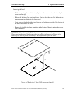
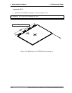
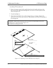
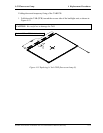
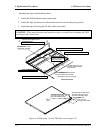
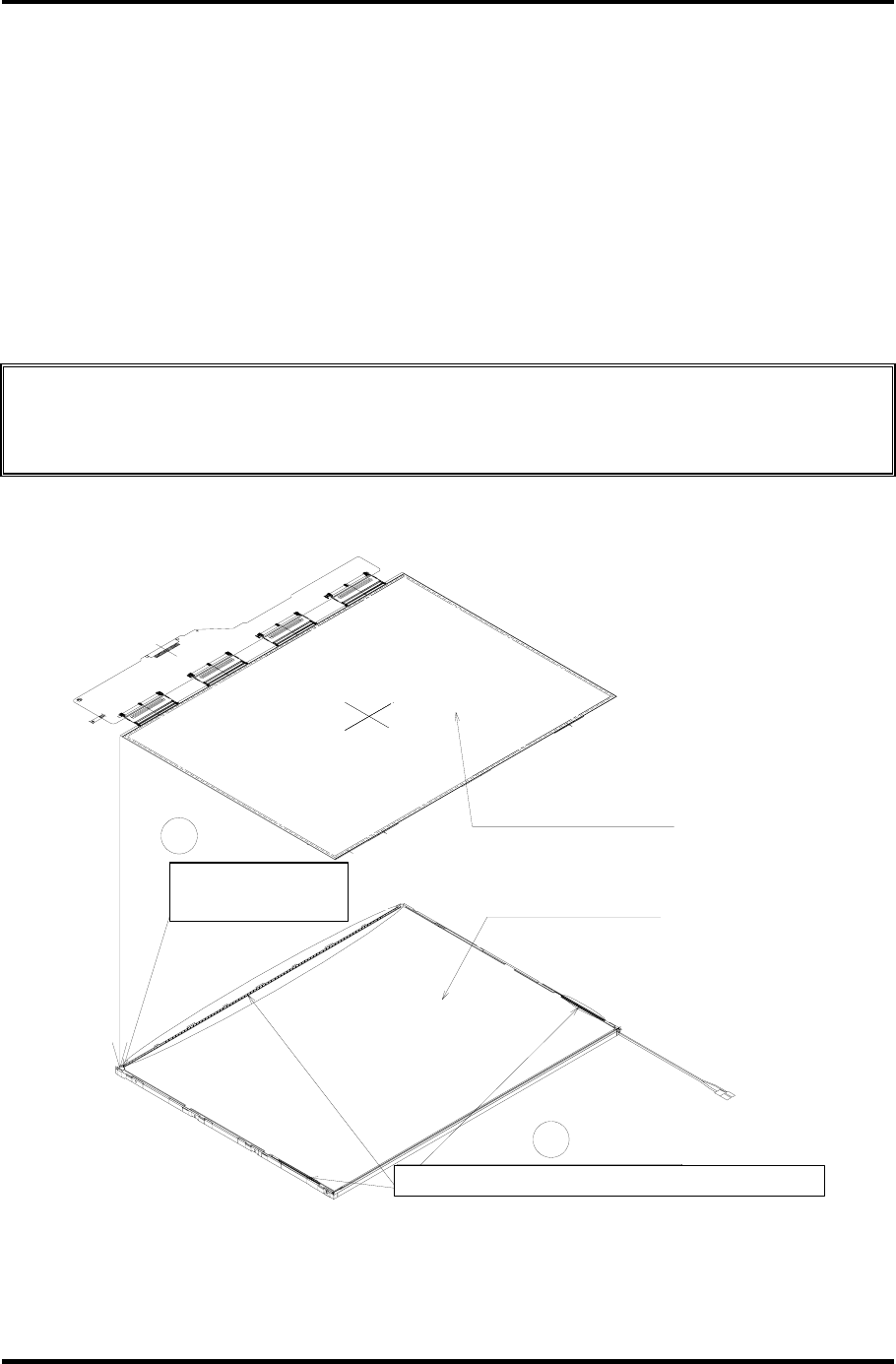
1. Remove the paper (coated with a mold release) from the double-sided tape in the
three areas on the replacement backlight unit. The areas are at the top and on both
sides. See Figure 4-52.
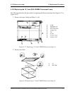
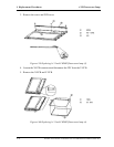
2. Turn the backlight on.
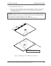
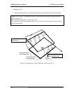
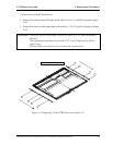
3. Check that the backlight is free of dust, foreign objects, or damage. Perform this
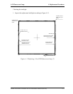
check also for the reverse side of the cell. Then install the cell of the PCB assembly in
the backlight unit.
CAUTION: Align the top left corner of the cell with the corresponding corner of the
backlight unit, as indicated by
②
in Figure 4-52.
Be careful not to damage the TAB.
2
1
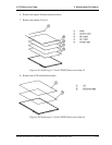
両面テープ剥離紙とる:3箇所
左上突き当て
PCB付きセル
バックライト
Cell of PCB
Backlight
Align the top left
corner.
Remove the paper on the double-side tape (three locations).
Figure 4- 52 Replacing 14 Inch TMD fluorescent lamp (8)
4-72 Satellite A10/TECRA A1/Satellite Pro A10 Maintenance Manual (960-445)