


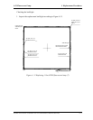
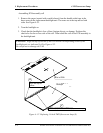
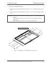
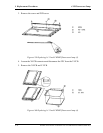
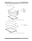
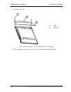
4.18 Fluorescent Lamp 4 Replacement Procedures
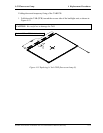
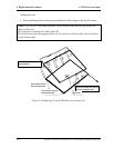
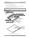
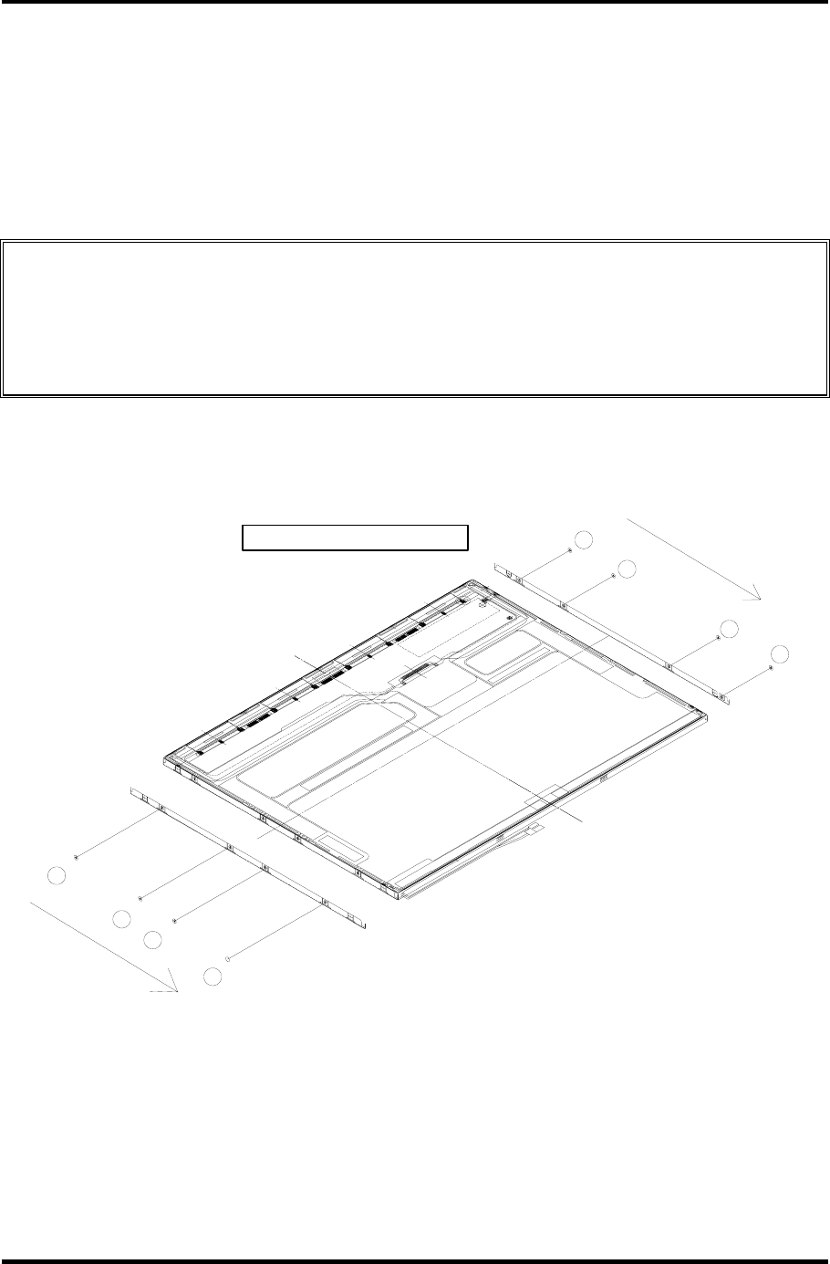
Fasten screws of the PCB and bezel
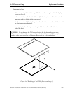
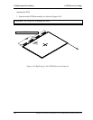
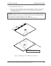
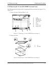
1. Fasten four screws on the left edge in the order (5), (6), (7), and (8) shown in Figure
4-55.
2. Fasten four screws on the right edge in the order (1), (2), (3), and (4) shown in Figure
4-55.
CAUTION: Fasten the screws in the orders shown in Figure 4-55. No loose fastening is
allowed.
The tightening torque must not exceed 0.147
N・
m (1.5kgf
・
cm) for all the
eight screws.
For the Philips screwdrivers, use an insert bit of point size 0.
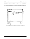
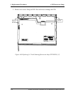
8
7
6
5
2
3
ネジ(M2X2.2)8箇所しめる
4
1
Fasten the ei
g
ht M2
×
2.2
Figure 4-55 Replacing 14 Inch TMD fluorescent lamp (11)
Satellite A10/TECRA A1/Satellite Pro A10 Maintenance Manual (960-445) 4-75