


4 Replacement Procedures 4.13 System Board/DC-IN Jack/RTC Battery
4.13 System Board/DC-IN Jack/RTC Battery
CAUTION: 1. When handling the system board, always hold by the edges. Do not touch
the printed circuit face.
2. After replacing the system board with a new one, set the DMI information
as described in section 3.4 “System test”. Also update with the latest BIOS as
described in Appendix G “BIOS/KBC/EC Update”.
3. After replacing the system board, the DMI information must be updated.
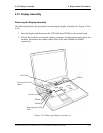
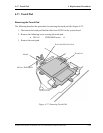
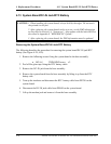
Removing the System Board/DC-IN Jack/RTC Battery
The following describes the procedure for removing the system board/DC-IN jack/RTC
battery (See Figure 4-29, 4-30).
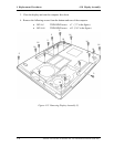
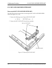
1. Remove the following screws fixing the system board to the base assembly.
• M2.5x5 THIN BIND screw x2
2. Peel off the glass tape fixing the RTC battery cable.
3. Remove the DC-IN jack from the base assembly.
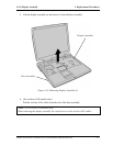
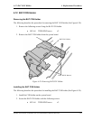
4. Remove the system board from the base assembly by lifting it up from the RTC
battery side.
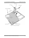
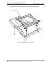
5. Turn up the insulator and disconnect the RTC battery cable from PJ8790 on the
system board.
6. Disconnect the DC-IN jack cable from PJ8800 on the system board.
7. Lift up the modem jack and remove it from the base assembly.
4-42 Satellite A10/TECRA A1/Satellite Pro A10 Maintenance Manual (960-445)