


1-11
DLDP Configuration Example
Network requirements
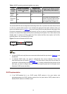
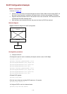
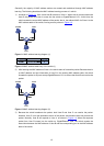
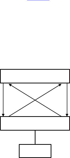
As shown in Figure 1-4,
z Switch A and Switch B are connected through two pairs of fibers. Both of them support DLDP. All
the ports involved operate in mandatory full duplex mode, with their rates all being 1,000 Mbps.
z Suppose the fibers between Switch A and Switch B are cross-connected. DLDP disconnects the
unidirectional links after detecting them.
z After the fibers are connected correctly, the ports shut down by DLDP are restored.
Network diagram
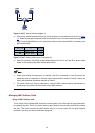
Figure 1-4 Network diagram for DLDP configuration
Device A
GE1/0/49
GE1/0/50
Device B
GE1/0/49 GE1/0/50
PC
Configuration procedure
1) Configure Switch A
# Configure the ports to work in mandatory full duplex mode at a rate of 1000 Mbps.
<SwitchA> system-view
[SwitchA] interface gigabitethernet 1/0/49
[SwitchA-GigabitEthernet1/0/49] duplex full
[SwitchA-GigabitEthernet1/0/49] speed 1000
[SwitchA-GigabitEthernet1/0/49] quit
[SwitchA] interface gigabitethernet 1/0/50
[SwitchA-GigabitEthernet1/0/50] duplex full
[SwitchA-GigabitEthernet1/0/50] speed 1000
[SwitchA-GigabitEthernet1/0/50] quit
# Enable DLDP globally
[SwitchA] dldp enable
# Set the interval between sending DLDP packets to 15 seconds.
[SwitchA] dldp interval 15
# Configure DLDP to work in enhanced mode
[SwitchA] dldp work-mode enhance