


2-6
Network diagram
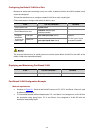
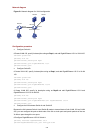
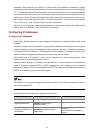
Figure 2-1 Network diagram for VLAN configuration
SwitchA
SwitchB
PC1 PC2
GE1/0/1
GE1/0/2
GE1/0/10
GE1/0/11
GE1/0/12
GE1/0/13
Server2 Server1
Configuration procedure
z Configure Switch A.
# Create VLAN 100, specify its descriptive string as Dept1, and add GigabitEthernet 1/0/1 to VLAN 100.
<SwitchA> system-view
[SwitchA] vlan 100
[SwitchA-vlan100] description Dept1
[SwitchA-vlan100] port GigabitEthernet 1/0/1
[SwitchA-vlan100] quit
z Configure Switch B.
# Create VLAN 100, specify its descriptive string as Dept1, and add GigabitEthernet 1/0/13 to VLAN
100.
<SwitchB> system-view
[SwitchB] vlan 100
[SwitchB-vlan100] description Dept1
[SwitchB-vlan100] port GigabitEthernet 1/0/13
[SwitchB-vlan103] quit
# Create VLAN 200, specify its descriptive string as Dept2 and add GigabitEthernet 1/0/11 and
GigabitEthernet 1/0/12 to VLAN 200.
[SwitchB] vlan 200
[SwitchB-vlan200] description Dept2
[SwotchB-vlan200] port GigabitEthernet1/0/11 GigabitEthernet 1/0/12
[SwitchB-vlan200] quit
z Configure the link between Switch A and Switch B.
Because the link between Switch A and Switch B needs to transmit data of both VLAN 100 and VLAN
200, you can configure the ports at both ends of the link as trunk ports and permit packets of the two
VLANs to pass through the two ports.
# Configure GigabitEthernet 1/0/2 of Switch A.
[SwitchA] interface GigabitEthernet 1/0/2
[SwitchA-GigabitEthernet1/0/2] port link-type trunk