


1-27
z After completing the above configuration, you can execute the cluster switch-to
{ member-number | mac-address H-H-H } command on the management device to switch to
member device view to maintain and manage a member device. After that, you can execute the
cluster switch-to administrator command to return to management device view.
z In addition, you can execute the reboot member { member-number | mac-address H-H-H }
[ eraseflash ] command on the management device to reboot a member device. For detailed
information about these operations, refer to the preceding description in this chapter.
z After the above configuration, you can receive logs and SNMP trap messages of all cluster
members on the NMS.
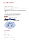
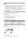
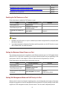
Network Management Interface Configuration Example
Network requirements
z Configure VLAN-interface 2 as the network management interface of the switch;
z Configure VLAN 3 as the management VLAN;
z The IP address of the FTP server is 192.168.4.3;
z Switch A operates as the management switch;
z Switch B and Switch C are member switches.
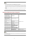
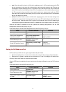
Table 1-2 Connection information of the management switch
VLAN IP address Connection port
VLAN 3 (connected to Switch
B)
192.168.5.30/24 Ethernet 1/0/1
VLAN 2 (connected to FTP
server)
192.168.4.22/24 Ethernet 1/0/2
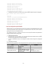
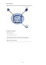
Network diagram
Figure 1-5 Network diagram for network management interface configuration
Configuration procedure
# Enter system view and configure VLAN 3 as the management VLAN.