


1-6
VLAN-VPN Configuration Example
Transmitting User Packets through a Tunnel in the Public Network by Using
VLAN-VPN
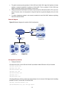
Network requirements
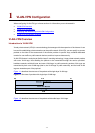
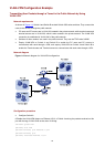
As shown in Figure 1-4, Switch A and Switch B are both Switch 4500 series switches. They connect the
users to the servers through the public network.
z PC users and PC servers are in VLAN 100 created in the private network, while terminal users and
terminal servers are in VLAN 200, which is also created in the private network. The VLAN VPN
connection is established in VLAN 1040 of the public network.
z Switches of other vendors’ are used in the public network. They use the TPID value 0x9200.
z Employ VLAN-VPN on Switch A and Switch B to enable the PC users and PC servers to
communicate with each through a VPN, and employ VLAN-VPN on Switch A and Switch B to
enable the Terminal users and Terminal servers to communicate with each other through a VPN.
Network diagram
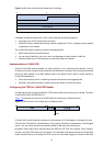
Figure 1-4 Network diagram for VLAN-VPN configuration
Configuration procedure
z Configure Switch A.
# Enable the VLAN-VPN feature on Ethernet 1/0/11 of Switch A and tag the packets received on this
port with the tag of VLAN 1040 as the outer VLAN tag.
<SwitchA> system-view
[SwitchA] vlan 1040
[SwitchA-vlan1040] port Ethernet 1/0/11
[SwitchA-vlan1040] quit
[SwitchA] interface Ethernet 1/0/11