


1-20
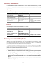
Network diagram
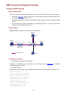
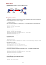
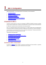
Figure 3-4 Network diagram for multicast VLAN configuration
WorkStation SwitchA
SwitchB
Vlan-int20
168.10.1.1
Eth1/0/1
Eth1/0/10
V
l
a
n2
V
l
an3
Eth1/0/10
Vlan10
E
th1/0/1
E
th1/0/2
HostA
HostB
Vlan-int10
168.10.2.1
Configuration procedure
The following configuration is based on the prerequisite that the devices are properly connected and all
the required IP addresses are already configured.
1) Configure Switch A:
# Set the interface IP address of VLAN 20 to 168.10.1.1 and enable PIM DM on the VLAN interface.
<SwitchA> system-view
[SwitchA] multicast routing-enable
[SwitchA] vlan 20
[SwitchA–vlan20]port Ethernet 1/0/1
[SwitchA-vlan20] quit
[SwitchA] interface Vlan-interface 20
[SwitchA-Vlan-interface20] ip address 168.10.1.1 255.255.255.0
[SwitchA-Vlan-interface20] pim dm
[SwitchA-Vlan-interface20] quit
# Configure VLAN 10.
[SwitchA] vlan 10
[SwitchA-vlan10] quit
# Define Ethernet 1/0/10 as a hybrid port, add the port to VLAN 10, and configure the port to forward
tagged packets for VLAN 10.
[SwitchA] interface Ethernet 1/0/10
[SwitchA-Ethernet1/0/10] port link-type hybrid
[SwitchA-Ethernet1/0/10] port hybrid vlan 10 tagged
[SwitchA-Ethernet1/0/10] quit
# Configure the interface IP address of VLAN 10 as 168.10.2.1, and enable PIM-DM and IGMP.
[SwitchA] interface Vlan-interface 10
[SwitchA-Vlan-interface10] ip address 168.10.2.1 255.255.255.0
[SwitchA-Vlan-interface10] igmp enable
[SwitchA-Vlan-interface10] pim dm
2) Configure Switch B:
# Enable the IGMP Snooping feature on Switch B.
<SwitchB> system-view
[SwitchB] igmp-snooping enable