


1-24
Cluster Configuration Examples
Basic Cluster Configuration Example
Network requirements
Three switches compose a cluster, where:
z A Switch 4500 series switch serves as the management device.
z The rest are member devices.
Serving as the management device, the Switch 4500 switch manages the two member devices. The
configuration for the cluster is as follows:
z The two member devices connect to the management device through Ethernet 1/0/2 and Ethernet
1/0/3.
z The management device connects to the Internet through Ethernet 1/0/1.
z Ethernet 1/0/1 belongs to VLAN 2, whose interface IP address is 163.172.55.1.
z All the devices in the cluster share the same FTP server and TFTP server.
z The FTP server and TFTP server use the same IP address: 63.172.55.1.
z The NMS and logging host use the same IP address: 69.172.55.4.
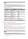
Network diagram
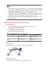
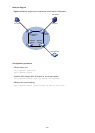
Figure 1-4 Network diagram for HGMP cluster configuration
Internet
Eth 1/0/1
Et h 1/0/ 3 E th 1/0/2
Eth 1/ 0/1 Eth 1/0/1
69.172.55.4
SNMP/logging host(NMS)
FTP/TFTP Server
63.172.55.1
163.172.55.1
VLAN-interface 2
Management
device
Cluster
Member device
MAC:000f.e201.0011 MAC:000f.e201. 0012
Member device
Configuration procedure
1) Configure the member devices (taking one member as an example)
# Enable NDP globally and on Ethernet 1/0/1.
<Sysname> system-view
[Sysname] ndp enable
[Sysname] interface Ethernet 1/0/1
[Sysname-Ethernet1/0/1] ndp enable
[Sysname-Ethernet1/0/1] quit
# Enable NTDP globally and on Ethernet 1/0/1.