


1-28
<Sysname> system-view
[Sysname] management-vlan 3
# Add Ethernet 1/0/1 to VLAN 3.
[Sysname] vlan 3
[Sysname-vlan3] port Ethernet 1/0/1
[Sysname-vlan3] quit
# Set the IP address of VLAN-interface 3 to 192.168.5.30.
[Sysname] interface Vlan-interface 3
[Sysname-Vlan-interface3] ip address 192.168.5.30 255.255.255.0
[Sysname-Vlan-interface3] quit
# Add Ethernet 1/0/2 to VLAN 2.
[Sysname] vlan 2
[Sysname-vlan2] port Ethernet 1/0/2
[Sysname-vlan2] quit
# Set the IP address of VLAN-interface 2 to 192.168.4.22.
[Sysname] interface Vlan-interface 2
[Sysname-Vlan-interface2] ip address 192.168.4.22 255.255.255.0
[Sysname-Vlan-interface2] quit
# Enable the cluster function.
[Sysname] cluster enable
# Enter cluster view.
[Sysname] cluster
[Sysname-cluster]
# Configure a private IP address pool for the cluster. The IP address pool contains 30 IP addresses,
starting from 192.168.5.1.
[Sysname-cluster] ip-pool 192.168.5.1 255.255.255.224
# Name and build the cluster.
[Sysname-cluster] build aaa
[aaa_0.Sysname-cluster]
# Configure VLAN-interface 2 as the network management interface.
[aaa_0.Sysname] cluster
[aaa_0.Sysname-cluster] nm-interface Vlan-interface 2
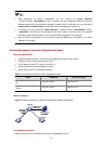
Enhanced Cluster Feature Configuration Example
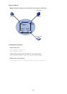
Network requirements
z The cluster operates properly.
z Add the device with the MAC address 0001-2034-a0e5 to the cluster blacklist, that is, prevent the
device from being managed and maintained by the cluster.
z Save the current cluster topology as the base topology and save it in the flash of the local
management device in the cluster.