


1-14
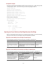
z Forwarding state. Ports in this state can forward user packets and receive/send BPDU packets.
z Learning state. Ports in this state can receive/send BPDU packets but do not forward user packets.
z Discarding state. Ports in this state can only receive BPDU packets.
Port roles and port states are not mutually dependent.
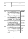
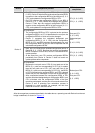
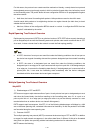
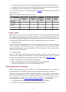
Table 1-6 lists possible combinations of port
states and port roles.
Table 1-6 Combinations of port states and port roles
Port role
Port state
Root/master
port
Designated
port
Region
Boundary
port
Alternate
port
Backup
port
Forwarding √ √ √ — —
Learning √ √ √ — —
Discarding √ √ √ √ √
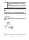
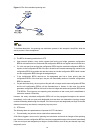
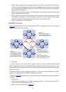
Principle of MSTP
MSTP divides a Layer 2 network into multiple MST regions. The CSTs are generated between these
MST regions, and multiple spanning trees (also called MSTIs) can be generated in each MST region. As
well as RSTP, MSTP uses configuration BPDUs for spanning tree calculation. The only difference is that
the configuration BPDUs for MSTP carry the MSTP configuration information on the switches.
1) Calculate the CIST
Through comparing configuration BPDUs, the switch of the highest priority in the network is selected as
the root of the CIST. In each MST region, an IST is calculated by MSTP. At the same time, MSTP
regards each MST region as a switch to calculate the CSTs of the network. The CSTs, together with the
ISTs, form the CIST of the network.
2) Calculate an MSTI
Within an MST region, MSTP generates different MSTIs for different VLANs based on the
VLAN-to-instance mappings. MSTP performs a separate calculation process, which is similar to
spanning tree calculation in STP, for each spanning tree. For details, refer to
How STP works.
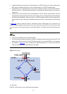
In MSTP, a VLAN packet is forwarded along the following paths:
z Within an MST region, the packet is forwarded along the corresponding MSTI.
z Between two MST regions, the packet is forwarded along the CST.
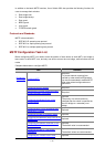
MSTP Implementation on Switches
MSTP is compatible with both STP and RSTP. That is, MSTP-enabled switches can recognize the
protocol packets of STP and RSTP and use them for their respective spanning tree calculation.
The 3com switches 4500 support MSTP. After MSTP is enabled on a switch 4500, the switch operates
in MSTP mode by default. If the network contains switches that run the STP/RSTP protocol, you can
use commands to configure the switches 4500 to operate in STP-compatible mode or
RSTP-compatible mode (see
Configuring the MSTP Operation Mode for more information):
z In STP-compatible mode, all ports of the switches 4500 send out STP BPDUs
z In RSTP mode, all ports of the switches 4500 send out RSTP BPDUs.