


1-17
IGMP Snooping Configuration Examples
Configuring IGMP Snooping
Network requirements
To prevent multicast traffic from being flooded at Layer 2, enable IGMP snooping on Layer 2 switches.
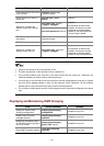
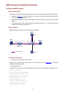
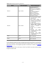
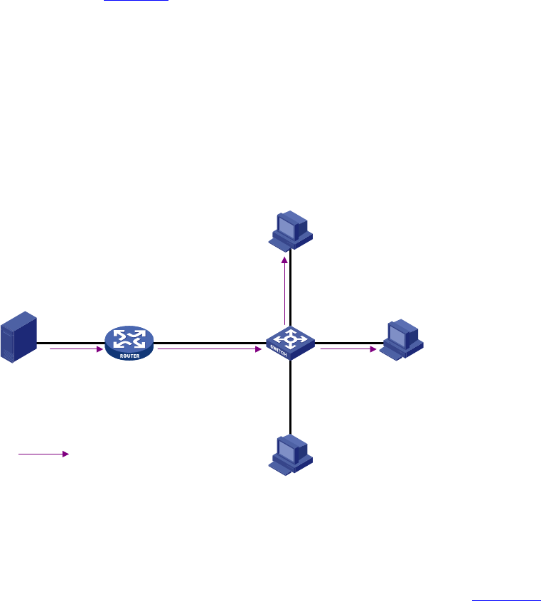
z As shown in Figure 3-3, Router A connects to a multicast source (Source) through Ethernet 1/0/2,
and to Switch A through Ethernet 1/0/1.
z Run PIM-DM and IGMP on Router A. Run IGMP snooping on Switch A. Router A acts as the IGMP
querier.
z The multicast source sends multicast data to the multicast group 224.1.1.1. Host A and Host B are
receivers of the multicast group 224.1.1.1.
Network diagram
Figure 3-3 Network diagram for IGMP Snooping configuration
Multicast packets
Source
Router A Switch A
Receiver
Receiver
Host B
Host A
Host C
1.1.1.1/24
Eth1/0/4
Eth1/0/2
Eth1/0/3
IGMP querier
Eth1/0/1
Eth1/0/1
10.1.1.1/24
Eth1/0/2
1.1.1.2/24
VLAN100
Configuration procedure
1) Configure the IP address of each interface
Configure an IP address and subnet mask for each interface as per
Figure 3-3. The detailed
configuration steps are omitted.
2) Configure Router A
# Enable IP multicast routing, enable PIM-DM on each interface, and enable IGMP on Ethernet 1/0/1.
<RouterA> system-view
[RouterA] multicast routing-enable
[RouterA] interface Ethernet 1/0/1
[RouterA-Ethernet1/0/1] igmp enable
[RouterA-Ethernet1/0/1] pim dm
[RouterA-Ethernet1/0/1] quit
[RouterA] interface Ethernet 1/0/2
[RouterA-Ethernet1/0/2] pim dm
[RouterA-Ethernet1/0/2] quit