


1-6
Step Description
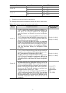
3
The device compares the calculated configuration BPDU with the configuration BPDU
on the port whose role is to be determined, and acts as follows based on the
comparison result:
z If the calculated configuration BPDU is superior, this port will serve as the
designated port, and the configuration BPDU on the port will be replaced with the
calculated configuration BPDU, which will be sent out periodically.
z If the configuration BPDU on the port is superior, the device stops updating the
configuration BPDUs of the port and blocks the port, so that the port only receives
configuration BPDUs, but does not forward data or send configuration BPDUs.
When the network topology is stable, only the root port and designated ports forward traffic, while other
ports are all in the blocked state – they only receive STP packets but do not forward user traffic.
Once the root bridge, the root port on each non-root bridge, and designated ports have been
successfully elected, the entire tree-shaped topology has been constructed. At this stage, “STP
convergence” is complete.
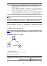
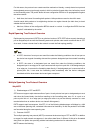
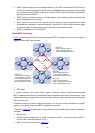
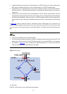
2) Example of how the STP algorithm works
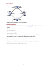
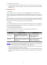
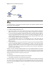
The following is an example of how the STP algorithm works. The specific network diagram is shown in
Figure 1-2. The priority of Device A is 0, the priority of Device B is 1, the priority of Device C is 2, and the
path costs of these links are 5, 10 and 4 respectively.
Figure 1-2 Network diagram for STP algorithm
z Initial state of each device
The following table shows the initial state of each device.
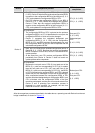
Table 1-4 Initial state of each device
Device Port name BPDU of port
AP1 {0, 0, 0, AP1}
Device A
AP2 {0, 0, 0, AP2}