


1-19
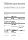
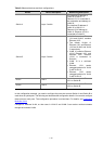
Table 3-2 Network devices and their configurations
Device Device description Networking description
Switch A Layer 3 switch
The interface IP address of
VLAN 20 is 168.10.1.1.
Ethernet 1/0/1 is connected to
the workstation and belongs to
VLAN 20.
The interface IP address of
VLAN 10 is 168.10.2.1.
Ethernet 1/0/10 belongs to
VLAN 10. Ethernet 1/0/10 is
connected to Switch B.
Switch B Layer 2 switch
z VLAN 2 contains Ethernet
1/0/1 and VLAN 3 contains
Ethernet 1/0/2.
z The default VLANs of
Ethernet 1/0/1 and Ethernet
1/0/2 are VLAN 2 and VLAN
3 respectively.
z VLAN 10 contains Ethernet
1/0/10, Ethernet 1/0/1, and
Ethernet 1/0/2. Ethernet
1/0/10 is connected to
Switch A.
z VLAN 10 is a multicast
VLAN.
z Ethernet 1/0/1 sends
untagged packets for VLAN
2 and VLAN 10.
z Ethernet 1/0/2 sends
untagged packets for VLAN
3 and VLAN 10.
Host A User 1
Host A is connected to Ethernet
1/0/1 on Switch B.
Host B User 2
Host B is connected to Ethernet
1/0/2 on Switch B.
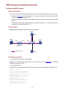
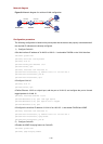
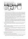
In this configuration example, you need to configure the ports that connect Switch A and Switch B to
each other as hybrid ports. The following text describes the configuration details. You can also configure
these ports as trunk ports. The configuration procedure is omitted here. For details, see
Configuring
Multicast VLAN
.
Configure a multicast VLAN, so that users in VLAN 2 and VLAN 3 can receive multicast streams
through the multicast VLAN.