


1-9
Ethernet1/0/1 both
Ethernet1/0/2 both
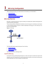
monitor port: Ethernet1/0/3
After the configurations, you can monitor all packets received on and sent from the R&D department
and the marketing department on the data detection device.
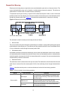
Remote Port Mirroring Configuration Example
Network requirements
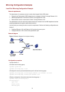
The departments of a company connect to each other through Switch 4500 series:
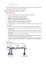
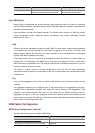
z Switch A, Switch B, and Switch C are Switch 4500 series.
z Department 1 is connected to Ethernet 1/0/1 of Switch A.
z Department 2 is connected to Ethernet 1/0/2 of Switch A.
z Ethernet 1/0/3 of Switch A connects to Ethernet 1/0/1 of Switch B.
z Ethernet 1/0/2 of Switch B connects to Ethernet 1/0/1 of Switch C.
z The data detection device is connected to Ethernet 1/0/2 of Switch C.
The administrator wants to monitor the packets sent from Department 1 and 2 through the data
detection device.
Use the remote port mirroring function to meet the requirement. Perform the following configurations:
z Use Switch A as the source switch, Switch B as the intermediate switch, and Switch C as the
destination switch.
z On Switch A, create a remote source mirroring group, configure VLAN 10 as the remote-probe
VLAN, ports Ethernet 1/0/1 and Ethernet 1/0/2 as the source ports, and port Ethernet 1/0/4 as the
reflector port.
z On Switch B, configure VLAN 10 as the remote-probe VLAN.
z Configure Ethernet 1/0/3 of Switch A, Ethernet 1/0/1 and Ethernet 1/0/2 of Switch B, and Ethernet
1/0/1 of Switch C as trunk ports, allowing packets of VLAN 10 to pass.
z On Switch C, create a remote destination mirroring group, configure VLAN 10 as the remote-probe
VLAN, and configure Ethernet 1/0/2 connected with the data detection device as the destination
port.
Network diagram
Figure 1-4 Network diagram for remote port mirroring