


1-3
Access Management Configuration Examples
Access Management Configuration Example
Network requirements
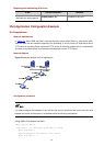
Client PCs are connected to the external network through Switch A (an Ethernet switch).
The IP addresses of the PCs of Organization 1 are in the range 202.10.20.1/24 to
202.10.20.20/24. The IP address of PC 2 is 202.10.20.100/24, and that of PC 3 is
202.10.20.101/24.
z Allow the PCs of Organization 1 to access the external network through Ethernet 1/0/1
on Switch A. The port belongs to VLAN 1, and the IP address of VLAN-interface 1 is
202.10.20.200/24.
z Disable the PCs that are not of Organization 1 (PC 2 and PC 3) from accessing the
external network through Ethernet 1/0/1 of Switch A.
Network diagram
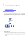
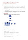
Figure 1-2 Network diagram for access management configuration
Switch A
Switch B
Eth1/0/1
PC1_1 PC1_2
PC1_20
PC 2 PC 3
Internet
202.10.20.1/24~202.10.20.20/24
Organization1
Vlan-int1
202.10.20.200/24
202.10.20.100/24 202.10.20.101/24
Configuration procedure
Perform the following configuration on Switch A.
# Enable access management.
<Sysname> system-view
[Sysname] am enable
# Set the IP address of VLAN-interface 1 to 202.10.20.200/24.
[Sysname] interface Vlan-interface 1
[Sysname-Vlan-interface1] ip address 202.10.20.200 24
[Sysname-Vlan-interface1] quit
# Configure the access management IP address pool on Ethernet 1/0/1.
[Sysname] interface Ethernet 1/0/1