


1-25
Configuration Example of Priority Marking and Queue Scheduling
Network requirements
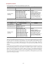
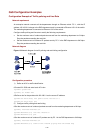
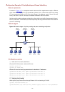
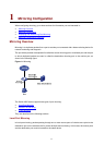
As shown in Figure 1-10, an enterprise network connects all the departments through an Ethernet
switch. Clients PC 1 through PC 3 are connected to Ethernet 1/0/1 of the switch; clients PC 4 through
PC 6 are connected to Ethernet 1/0/3 of the switch. Server 1 (the database server), Server 2 (the mail
server), and Server 3 (the file server) are connected to Ethernet 1/0/2 of the switch.
Configure priority marking and queue scheduling on the switch to mark traffic flows accessing Server 1,
Server 2, and Server 3 with different priorities respectively and assign the three traffic flows to different
queues for scheduling.
Network diagram
Figure 1-10 Network diagram for priority marking and queue scheduling configuration
PC 3PC 2PC 1
Switch
Eth1/0/1
Server 1
192.168.0.1
PC 6
Eth1/0/2
Server 2
192.168.0.2
Server 3
192.168.0.3
PC 5PC 4
Eth1/0/3
Configuration procedure
1) Define an ACL for traffic classification
# Create ACL 3000 and enter advanced ACL view.
<Sysname> system-view
[Sysname] acl number 3000
# Define ACL rules for identifying packets based on destination IP addresses.
[Sysname-acl-adv-3000] rule 0 permit ip destination 192.168.0.1 0
[Sysname-acl-adv-3000] rule 1 permit ip destination 192.168.0.2 0
[Sysname-acl-adv-3000] rule 2 permit ip destination 192.168.0.3 0
[Sysname-acl-adv-3000] quit
2) Configure priority marking
# Mark priority for packets received through Ethernet 1/0/2 and matching ACL 3000.
[Sysname] interface Ethernet1/0/2
[Sysname-Ethernet1/0/2] traffic-priority inbound ip-group 3000 rule 0 local-precedence 4