


1-7
z Perform the following configuration on Switch A: setting the community name and access
permission, administrator ID, contact and switch location, and enabling the switch to sent traps.
Thus, the NMS is able to access Switch A and receive the traps sent by Switch A.
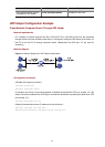
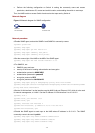
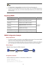
Network diagram
Figure 1-2 Network diagram for SNMP configuration
10.10.10.2/16
NMS
10.10.10.1/16
Switch A
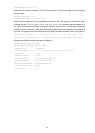
Network procedure
# Enable SNMP agent, and set the SNMPv1 and SNMPv2c community names.
<Sysname> system-view
[Sysname] snmp-agent
[Sysname] snmp-agent sys-info version all
[Sysname] snmp-agent community read public
[Sysname] snmp-agent community write private
# Set the access right of the NMS to the MIB of the SNMP agent.
[Sysname] snmp-agent mib-view include internet 1.3.6.1
# For SNMPv3, set:
z SNMPv3 group and user
z security to the level of needing authentication and encryption
z authentication protocol to HMAC-MD5
z authentication password to passmd5
z encryption protocol to DES
z encryption password to cfb128cfb128
[Sysname] snmp-agent group v3 managev3group privacy write-view internet
[Sysname] snmp-agent usm-user v3 managev3user managev3group authentication-mode md5 passmd5
privacy-mode des56 cfb128cfb128
# Set the VLAN-interface 2 as the interface used by NMS. Add port Ethernet 1/0/2, which is to be used
for network management, to VLAN 2. Set the IP address of VLAN-interface 2 as 10.10.10.2.
[Sysname] vlan 2
[Sysname-vlan2] port Ethernet 1/0/2
[Sysname-vlan2] quit
[Sysname] interface Vlan-interface 2
[Sysname-Vlan-interface2] ip address 10.10.10.2 255.255.255.0
[Sysname-Vlan-interface2] quit
# Enable the SNMP agent to send traps to the NMS whose IP address is 10.10.10.1. The SNMP
community name to be used is public.
[Sysname] snmp-agent trap enable standard authentication
[Sysname] snmp-agent trap enable standard coldstart
[Sysname] snmp-agent trap enable standard linkup