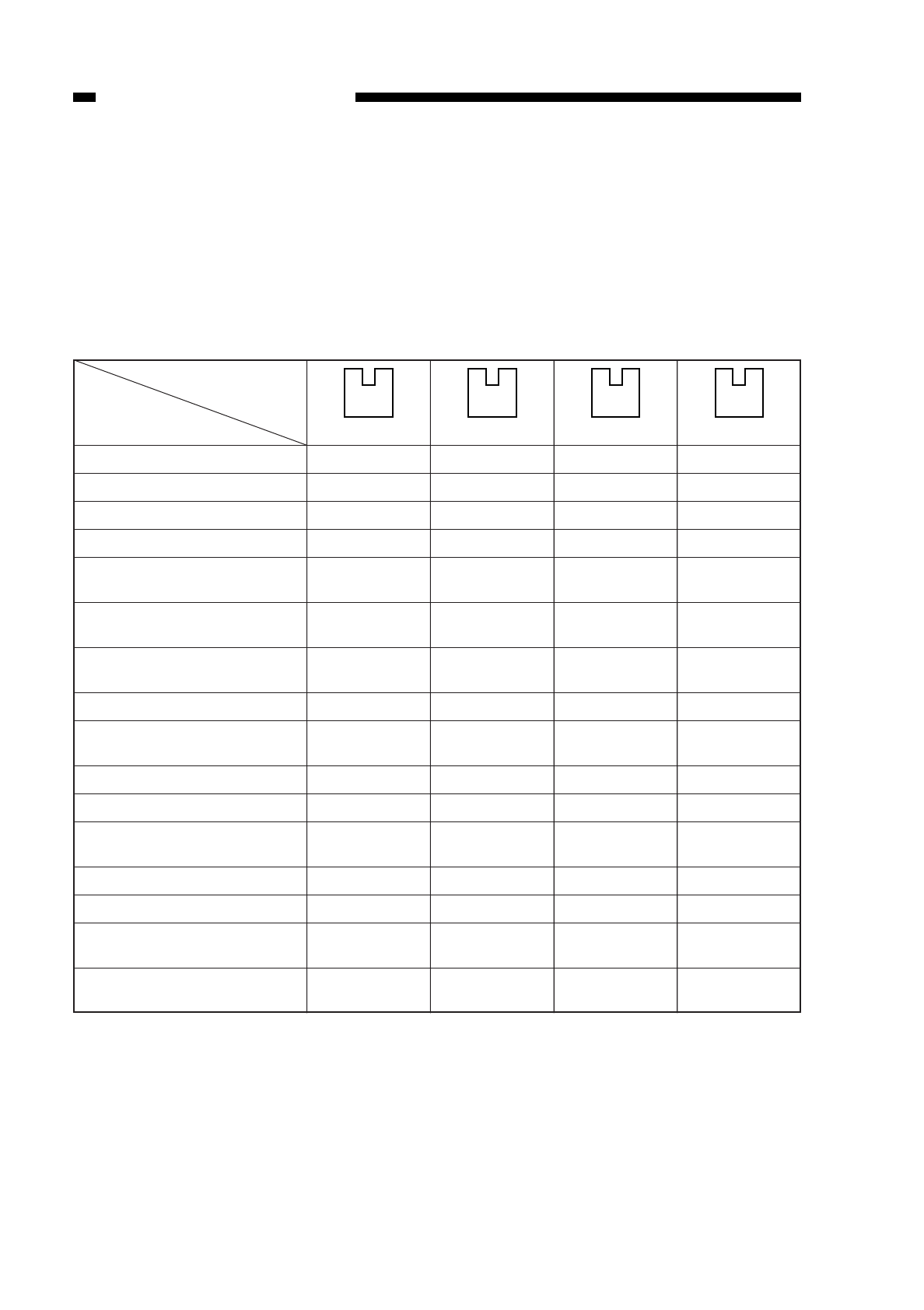
V. IDENTIFYING THE CASSETTE SIZE
When a cassette is set in the cassette holder, appropriate photointerrupters (Q651,
Q652, Q653, Q654) turn on or off.
The microprocessor on the DC controller PCB identifies the presence/absence of a
cassette based on the combinations of the photointerrupters which are either on or off
(Table 5-501); accordingly, the microprocessor controls where the scanner must be
reversed or when to execute blank exposure.
(unit: mm)
1: photointerrupter is blocking light.
0: photointerrupter is not blocking light.
*size may be stored; must be within the range specified in mm; for details, see p. 10-
43.
Table 5-501
(right)
0
1
0
1
0
1
0
1
0
1
0
1
0
1
0
1
0
0
1
1
0
0
1
1
0
0
1
1
0
0
1
1
0
0
0
0
1
1
1
1
0
0
0
0
1
1
1
1
(Left)
0
0
0
0
0
0
0
0
1
1
1
1
1
1
1
1
COPYRIGHT
©
1997 CANON INC. CANON NP6218 REV. 0 MAY 1997 PRINTED IN JAPAN (IMPRIME AU JAPON)
CHAPTER 5 PICK-UP/FEEDING SYSTEM
5-10
Arrangement
Cassette size
No cassette
B5R (182
× 257)
A4 (297 × 220)
A3 (297 × 420)
Mini (STMTR) 5.5" × 8.5"
(148 × 216)
Legal 8.5" × 14"
(356 × 216)
Letter 11" × 8.5"
(279 × 216)
A4R (210 × 297)
Letter R 8.5" × 11"
(216 × 279)
A5R (149 × 218)
A5 (218 × 149)
Mini-R (STMT) 8.5" × 5.5"
(216 × 148)
B5 (257 × 182)
B4 (364 × 257)
Ledger 11" × 17"
(182 × 257)
*U
(182 ~ 283 × 198 ~ 354)
Q651
Q652
Q653
Q654


