


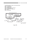
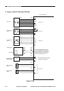
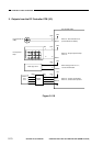

2. Inputs to the DC Controller PCB (2/3)
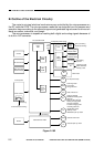
Figure 2-106
COPYRIGHT
©
1997 CANON INC. CANON NP6218 REV. 0 MAY 1997 PRINTED IN JAPAN (IMPRIME AU JAPON)
CHAPTER 2 BASIC OPERATION
2-6
See p. 6-1.
J651
-6
-5
-4
-3
-2
-1
J314
-7
-8
-9
-10
-11
-12
J313
-4
-5
-6
J304
-3
-4
J304
-1
-2
J309
J310
J801
J802
CS
CSZ_1
CSZ_2
CSZ_3
CSZ_4
Cassette size
sensor
Control panel
Main switch
Multifeeder paper
width detection
Main thermistor
(TH1)
Sub thermistor
(TH2)
See p. 5-8.
J601
-1
-2
-3
-4
J307
-7
-6
-5
-4
J604-2
-1
J356-1
-2
AE sensor
See p. 4-27.
See p. 4-4.
J701
-2
-4
-3
-1
J317
-3
-5
-4
-2
Light adjusting
sensor
AE
AEREF
AEVR1
AEVR2
+24V
+24V
+5V
L1D
MFPWD
TH1
TH2
VR1
SW829
DC controller PCB
On the control panel PCB, keys and
LEDs are arranged in a matrix; and
the DC controller turns on the LEDs or
reads key input. The main switch is
part of the control panel. (p. 7-2)
Detects the width of copy paper
loaded in the multifeeder.