E. Controlling the Transfer Roller Bias
1. Outline
The copier uses a direct transfer method by a roller to transfer images to paper. For
this reason, its bias control differs from that of conventional copiers, which transfer
images by corona charging.
The following three types of transfer roller bias are used; go through the
descriptions for the function and output timing of each.
a. Transfer Bias
This bias corresponds to the transfer bias of conventional copiers, and is a negative
voltage (constant voltage, –3.5 kV to –6.0 kVDC).
b. Cleaning Bias
Since the copier uses a direct transfer method, jams could cause toner on the
photosensitive drum to deposit itself on the transfer roller.
To remove such deposits of toner, the copier applies a positive voltage (constant
voltage, DC) at the following timing, thereby returning the toner from the transfer roller to
the photosensitive drum.
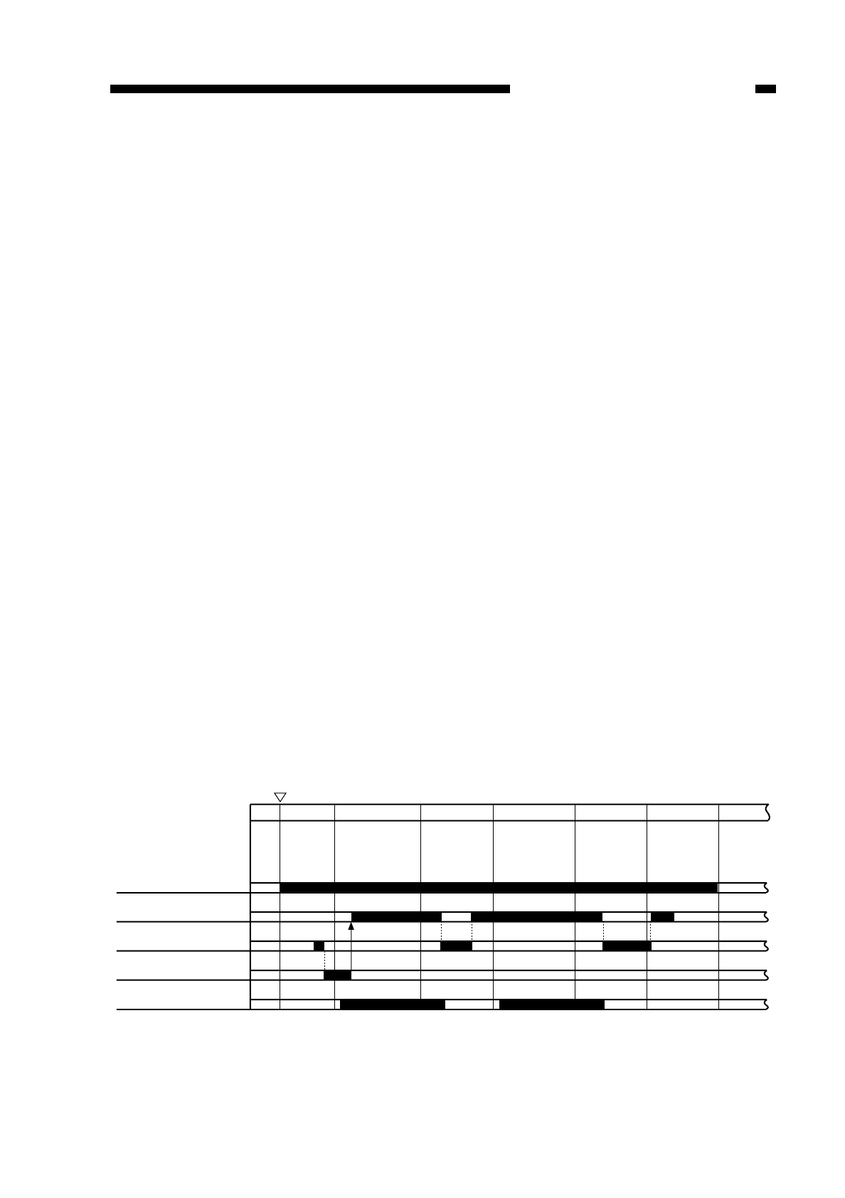
Cleaning Bias Output Timing
• during initial rotation after a press on the Copy Start key
• while the scanner is moving in reverse (certain period)
• during last rotation (certain period)
c. Reference Bias (ATVC)
Changes in the environment or deterioration of the transfer roller can affect the
resistance of the transfer roller, ultimately affecting the transfer efficiency.
To limit the changes in the image quality brought about by such changes in the
transfer efficiency, the copier corrects the application voltage level of the transfer bias.
The transfer ATVC bias (constant current, –10 µA DC) is the bias applied to
determine the correction value each time the Start button is pressed.
Figure 4-112
COPYRIGHT
©
1997 CANON INC. CANON NP6218 REV. 0 MAY 1997 PRINTED IN JAPAN (IMPRIME AU JAPON)
CHAPTER 4 IMAGE FORMATION SYSTEM
4-13
INTR
Copy Start key
ON
Main motor (M1)
Transfer bias
Cleaning bias (+)
Reference bias (ATVC)
Static eliminator bias
SCFW SCRV SCFW SCRV LSTR STRT


