


I. BASIC OPERATION
A. Varying the Reproduction Ratio
The reproduction ratio across the photosensitive drum is varied by the lens drive
system; on the other hand, the ratio around the drum is varied by the scanner drive
system.
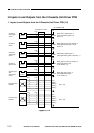
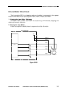
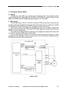
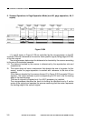
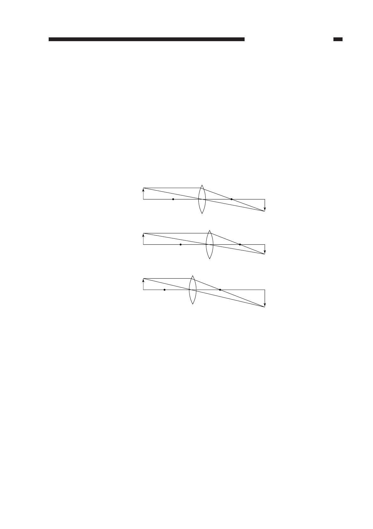
The lens drive system uses a zoom lens; as shown in Figure 3-101, the position and
focal distance of the lens are changed to vary the reproduction ratio across the
photosensitive drum.
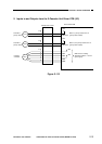
The scanner drive system varies the reproduction ratio around the photosensitive
drum by moving the No. 1 mirror relatively faster (reduction) or slower (enlargement) than
the peripheral speed of the photosensitive drum.
Figure 3-101
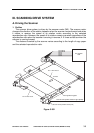
II. LENS DRIVE SYSTEM
A. Outline
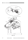
The lens drive system is driven by the lens motor (M3). The drive of the lens motor
is transmitted to the blank exposure unit through a relay gear. (See p. 4-18.)
When the lens is moved, the solenoid (SL1) is turned on to engage the relay gear
with the lens gear; when the lens motor rotates in the direction of the arrow in this
condition, the lens is moved in the direction of enlargement (
←) by the work of the relay
lens gear and lens cable.
The blank exposure shutter, on the other hand, moves according to the distance
traveled by the lens for reduction, thereby blanking (whiting) out the areas on both ends
of the copy.
The copier’s scanner lens home position sensor (PS2) is located at the center of the
scanner lens drive rail so that the scanner lens home position may be detected early
upon power-on, thereby speeding up the generation of the first copy. In addition, the
scanning lens moves to the appropriate position in response to a press on each ratio
button, thereby shortening the time it takes to generate the first copy.
COPYRIGHT
©
1997 CANON INC. CANON NP6218 REV. 0 MAY 1997 PRINTED IN JAPAN (IMPRIME AU JAPON)
CHAPTER 3 EXPOSURE SYSTEM
3-1
F
F'
F1
F2
F2'
F1'
Direct
Reduce
Enlarge